 Laser Head (A2074) Manual
© 2011-2021, Kevan Hashemi, Brandeis University© 2022-2023, Kevan Hashemi, Open Source Instruments Inc.
[12-OCT-23] The Laser Head (A2074) provides drive circuits for one or two laser diodes. The laser diodes must have the laser anode and photodiode cathode connected to the laser can, which is called the A-Type pinout or the LDA-PDC configuration. The drive circuits provide fast switching from off to full power, while at the same time providing complete protection of the laser diode from over-drive. We turn on the lasers by applying 7-15 V across the L+ and L− terminals of the drive circuit. The circuit monitors the laser's photodiode current and raises the laser diode current until the photodiode current reaches a level set by its photocurrent resistor. We describe how to set the laser output power in our NBCAM Laser Assembly Manual.

The lasers used with the A2074 must be housed in a three-pin package with the cathode of the laser diode and the anode of the photodiode connected in common to the case (see drawing). Examples of such lasers are LDP65001E (Lumex, now obsolete), DL3147 (Sanyo), L650P007 (Thorlabs), L658P040 (Thorlabs), and ADL65055TL (Arima). These are all red laser diodes. Their power outputs range from 5 mW to 65 mW, operating currents fom 35 mA to 150 mA, and forward voltages from 2.0 V and 2.7 V.

The A2074 is also suitable for driving infra-red laser diodes, and even green diode-pumped laser, such as the DJ532-10 (from Thorlabs). But we have not tested the A2074 with either infra-red or green diodes. In principle, the A2074 could drive a blue laser diode, but we have not found one with the correct internal connections for compatibility with the A2074.


In the figure above, the photocurrent resistor, R6 is 15 kΩ, which sets the output power of the LDP65001E laser diode on the other side to 4.0 mW. Note the orientation of the six-way flex connector. The contacts of the flex cable must face away from the board edge.
The six-way 1-mm flex socket on the A2074 has a pin-out compatible with switching circuits such as the Azimuthal BCAM Head (A2048), the Azimuthal Source Head (A2051S), and the Five-Way Injector Head (A2074A). The following versions of the A2074 exist.
| Version | Description |
|---|---|
| A2074A | Single Injector Laser Head (R7 = 10 Ω) |
| A2074B | Single Injector Laser Head (R7 = 22 Ω) |
| A2074C | Black N-BCAM Side Head, Dual Laser |
| A2074D | Blue N-BCAM Side Head, Dual Laser |
| A2074E | Black D-BCAM Side Head, Dual Laser |
| A2074F | Blue D-BCAM Side Head, Dual Laser |
Here is an A2074A shown attached to a focusing light injector assembly. Two lenses focus the laser light onto the tip of an optical fiber, which we adjust with a micrometer stage and then glue in place. The metal piece into which the A2074A is screwed must be anodized so as to isolate the laser can from the local ground.

The A3074A used 10 Ω for R7. The A3074B uses 22 Ω, which reduces intensity overshoot at turn-on for our newer lasers, and protects the circuit against over-heating in the case of laser failure. The A2074C and A2074D provide two laser diodes for the Black and Blue N-BCAMs respectively. For dimensions of the A2074C assembly, see here. The A2074D is a mirror image of the A2074C. In the A2074C/D we have R7 = R14 = 22 Ω, and calbration resistors R6 and R13 are initially set to 33 kΩ.
[22-DEC-11] The A2074 provides two independent laser drivers, as shown in the schematic. Each driver has two terminals, L+ and L− that provide power and control. There is no common connection between the two drivers. Laser LD1 turns on when voltage L1 is 7 V or higher. Laser LD2 turns on when L2 is 7 V or higher. Neither control voltage should exceed 15 V for laser currents up to 60 mA, or 10 V for laser currents up to 150 mA. Reverse voltages up to −30 V cause no damage to the circuit and do not turn on the laser. We discuss the operation of an eariler version of this circuit in detail here.
Circuits like the Five-Way Injector Head (A2073A) and Azimuthal Source Head (A2051S) LWDAQ devices designed to switch the lasers of an A2074. The A2073A switches only LD1, the first laser diode, which is all that is provided by the A2074A. These two circuits were designed to operate together: five A2074As are attached to a single A2073A. The A2073A connects 15 V through a single 47-Ω resistor to L1+ and 0 V through a MOSFET switch to L−. With the laser driver circuit drawing 100 mA, L1 will be 10.3 V, which means Q1 will dissipate 430 mW, which it can do indefinitely. If the laser driver draws 160 mA, which is what we would expect for a 65-mW red laser diode drawing 150 mA, L1 will drop to 8 V and Q1 will dissipate 300 mW.
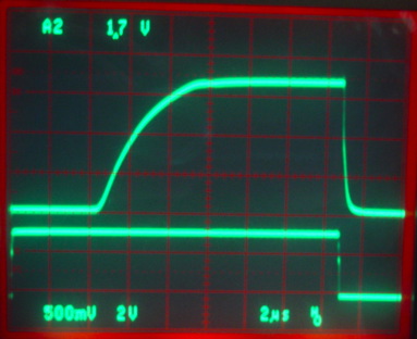
Capacitor C1 determines the turn-on delay for the laser drive. With C1 set to 22 nF the delay is 4 μs, as we can see in the following figure, in which we switch an LDP65001E laser from 0 mW to 4 mW.

Device like the A2073 and A2051 generate their switching logic pulse response to LWDAQ commands. A LWDAQ command takes 6.8 μs to transmit. We must use one to turn on a laser and another to turn it off, so the switching signal will be at least 6.8 μs long. In the figure above, we see the laser starting to turn on 4 μs after the switching signal is asserted, and reaching full power 5 μs after. The laser turns off in 200 ns. The shortest light pulse we can obtain with this 4-mW laser is around 2.5 μs.
If we set C1 to 47 nF, the turn-on is further delayed. We hoped to use a delayed turn-on to create tiny pulses like this one, but it turns out that increasing the turn-on delay beyond 6.8 μs endangers the laser. In the following figure we see a 6.8-μs turn-off period. The laser power drops to zero within 1 μs, but when we turn on the A2074 again, we see a spike in laser power before the proper turn-on.

During this spike, the A2074 feedback loop over-drives the laser for a few hundred nanoseconds. Our light sensor is not fast enough to detect the over-drive, but we are confident it occurs, because we destroyed half a dozen lasers with a few hundred thousand 6.8-μs off-periods when C1 was 47 ns. When we drop C1 to 22 nF, the spike goes away and millions of short off-periods do not damage the lasers.
If we wanted to modulate laser power from fully off to fully on more quickly, the circuit is stable with C1 as low as 4.7 nF, in which case the laser turns on within 1 μs of the switching pulse. Lower values of C1 create more bounce in the optical output power, and so endanger high-power lasers operating near their maximum operating power.
Higher-power lasers require more current from the laser driver, and the time to full power is longer. The following figure shows the A2074A switching an L658P040 laser from 0 mW to 40 mW.
The turn-on begins 4 μs after the switching signal, but the laser does not reach full power until 9 μs after. The laser does, however, turn off within 200 ns.
For a detailed description of the principles of this laser driver circuit, we refer you to our description of the near-identical laser driver circuit in the Azimuthal BCAM Side Head (A2049).
[11-MAR-13] We load an L650P007, 7-mW laser into the first laser driver of an A3026A, which uses the exact same laser driver as the A2074. We set R6 to 12 kΩ. We get 6 mW average optical power, as measured by our SD445 photodiode. We look at the light output versus time during light pulses, and obtain the following trace.

The light power over-shoots by 50%. We increase R7 to 22 Ω, so as to decrease the gain in the circuit's feedback loop. We get the following trace.

We see the overshoot is greatly reduced. We now try an L658P040, 40-mW laser, and set R6 to 68 kΩ for 6 mW average power. We turn on the laser repeatedly and observe the following traces.

The overshoot is small at turn-on. We see a spike during the subsequent turn-on, when we allow only 7 μs between pulses. But we see no damage to the laser after several million pulses, so we assume this spike does not over-drive the laser. The blurring of the intensity trace is an oscillation at 130 MHz in the laser current and light output. The the current through R7 oscillates between 40 mA and 50 mA. We now reduce R6 to 12 kΩ. Output power increases to 38 mW and the oscillations vanish.
When a laser diode fails, it no longer emits light. The laser driver circuit runs as much current as it can through the laser diode in an effort to make it emit light. In this case, with 15 V applied to the input of the laser driver, we will have 7 V across Q1, and 6 V accors LD1, Q2, and R7. The voltage at the base of Q2 will be 3 V minus the saturation voltage of the right-hand transistor in U1, say 2.8 V. The voltage on R7 will be 2.8 V minus the base-emitter trop of Q2, say 2.0 V. The A2074A has R7 = 10 Ω, in which case the current through the laser diode will be 200 mA. The diode itself will drop around 2.0 V, even though it is damaged. The diode, resistor, and transistor will each dissipate 0.4 W, which is enough to make them too hot to touch. The resistor will begin to melt the solder holding it to the printed circuit board. It is Q1 that suffers the most, however, with 200 mA and 7 V for a total of 1.4 W disspation. These FMMT491A transistors are rated at packages are rated at 500 mW.
If instead, as in the A2074B, we set R7 = 22 Ω, the maximum current through these three components drops to 91 mA, and the power dissipated in R7, Q2, and LD2 drops to 180 mW. The power in Q1 drops to 700 mW, which is too high, but not high enough to damage the component in a matter of minutes, as is the case for 1.4 W of dissipation.
[12-MAR-13] We try out a 40-mW laser with R6 = 68 kΩ in the A2074A circuit board, with R7 = 10 Ω. The layout of the tracks in the A2074A is far simpler than the longer traces of the A3026A. We think perhaps the inductance of these A3026A tracks causes the oscillations. The following trace shows the light versus time.

We change R7 to 22 Ω and look again.

The increase in R7 removes the overshoot, but we see the oscillations are present even with the A2074A layout. Their origin remains a mystery.
[27-NOV-15] We test the Black N-BCAM Side Head (A2074C) and ADL65055TL 5-mW laser diode. We have C1 = C2 = 22 nF, R7 = R14 = 22 Ω, and both R6 and R13 are 33 kΩ. Continuous power output from the laser is 1.5 mW. We obtain the following plots of light intensity versus time for increasing daq_flash_seconds in the BCAM Instrument.


Even with the 100% overshoot, power in the laser peaks at 3.0 mW, which is less than its rated 5 mW. We increase R7 to 47 Ω and obtain the following traces, in which overshoot is greatly diminished.

We have already built 100 A2074C and 150 A2074D with R7 = 22 Ω. We flashed repeatedly both laser diodes on an A2074C, where continuous power for both lasers is around 1.5 mW. We left R7 = 22 Ω, but changed R14 to 47 Ω. Flashes were roughly 100 μs at 50 kHz. After 400 million flashes, both diodes are unaffected.
The laser packages are metal and they are used for the anode of the laser diode itself and for the cathode of its photodiode. Thus the metal can must be connected to the laser driver circuit. There must be a direct-current path from the laser can to one of the power supplies in the circuit that provides power to the laser drivers. If we use the laser driver with any LWDAQ device, the LWDAQ grounding rules prohibit any direct-current connection between the device chassis and the device power supplies. Thus we must ensure that the laser cans are isolated from the chassis.

In devices like the BCAM, we provide isolation by means of non-conducting anodization of the chassis surface. The nominal diameter of the laser can is 3.55 mm. We use 3.7-mm diameter holes with 45° chamfers on both ends. These holes are snug enough to locate the laser package within ±80μm of their nominal position, and spacious enough to avoid any scratching of the anodized surface by stray fragments of aluminum oxide when we press the laser into the hole. We check every BCAM for a short circuit between the laser can and the chassis after assembly. No fresh BCAM chassis with a 3.7-mm hole has yet failed the test. But some recycled azimuthal BCAM chassis, from which we have knocked out lasers glued into their holes, have failed the test because the anodizing was damaged by the violent removal of the lasers. For more information about recycling BCAMs, see the BCAM Repair Manual.
[12-OCT-23] See our NBCAM Laser Assembly Manual for a detailed description laser calibration in N-BCAM versions of the A2074, which applies well to all other versions of the A2074 as well. In the paragraphs below, we explain how the laser driver works.
The laser driver increases the current in the laser diode until the voltage across the photocurrent resistor is 3 V. The photocurrent resistors for LD1 and LD2 are R6 and R13 respectively. By default, these will be 33 K, so that a photocurrent 90 μA will flow through the photocurrent resistor. Of this, roughly 10 μA will come from the base of the feedback transistor U1. That leaves 80 μA will flowing in the laser's photodiode. We assume that the photodiode current flowing when the laser is at its full, rated power is greater than 80 μA. This is the case for the laser diodes we list above.

To calibrate the laser drive circuit, we measure the power output of the laser for 80 μA of photocurrent and calcualte a new value of photocurrent resistor that will increase the optical power output to our target value. For example, suppose the optical power output is 2.0 mW and we want to drive the laser at 5 mW. We disconnect power from the drive circuit, remove the photocurrent resistor, and replace it with 15 kΩ. The photocurrent is now 190 μA (acconting for the 10 μA base current). We re-measure the optical power output and find it to be 4.75 mW. If that's close enough, we are done with our calibration. Otherwise we could drop the resistance a little.
When we focus laser light into an optical fiber with a 60-μm core, the pattern of light emerging from the far end of the fiber looks like this:

We suspect this pattern of bright and dark patches is due to the interference of coherent laser light that takes paths of different lengths in the multimode fiber. If so, it is in theory possible for the light intensity to be zero in some places and twice the average intensity in other places. We used a BCAM with 2-mm aperture, moving within the cone of light, to measure the local intensity of the pattern. We found that the minimum intensity was 10% of the maximum intensity. We suspect that the minimum intensity is 20% of the average intensity. If so, the minimum effective power of the fiber source for viewing by BCAMs will be 20% of the total power it emits. We have been calibrating our fiber sources to emit 1 mW. Their minimum effective power is 200 μW.
[11-JAN-12] We are using up our stock of several hundred LDP65001E lasers, installing these in our A2074As. Roughly one in ten fails during their first few hours of use after calibration. We set up a burn-in stand with an A2073A, and write a simple script to flash the lasers on and off every second. Here is a photograph of the setup with one laser failed after one hour of flashing.

Here is a close-up of the emission pattern at the far side of a focusing light injector without the optical fiber, the failed laser on the right.

The faulty laser in the photo above had an irregular emission stripe at the time of calibration. We observed in BCAM Assembly that lasers with irregular emission shapes, which are any shape other than a bright rectangle, have either cracked windows, damaged laser apertures, or excessive dirt on the window. We resolve to inspect the emission patterns of the lasers carefully before calibration, and to place each laser in our burn-in stand for at least twenty-four hours before we install the laser in any permanent fixture.
Note: All our schematics and Gerber files are distributed under the GNU General Public License.
S2074_1: Dual Laser Driver