This manual describes how to assemble a BCAM out of completed circuit boards and mechanical and optical components. We invite you to read our BCAM User Manual before moving on to reading the assembly procedures.
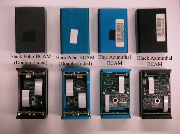
There are six BCAMs currently in production:
For more information regarding the differences and functions of these BCAMs, please refer to the User Manual.
The parts required when assembling a BCAM are listed below:
| Black Polar Single Ended | Black Polar Double Ended | Blue Polar Single Ended | Blue Polar Double Ended | Black Azimuthal | Blue Azimuthal |
|---|---|---|---|---|---|
| 2 of A2040L | 2 of A2040L | 2 of A2040R | 2 of A2040R | 1 of A2049L 1 of A2016L |
1 of A2049R 1 of A2016R |
| 1 of A2051R | 1 of A2051R | 1 of A2051L | 1 of A2051L | 1 of A2048L | 1 of A2048R |
| 2 of 12-way 2-in flex cable Digi-Key HF12U-02-ND |
2 of 12-way 2-in flex cable Digi-Key HF12U-02-ND |
2 of 12-way 2-in flex cable Digi-Key HF12U-02-ND |
2 of 12-way 2-in flex cable Digi-Key HF12U-02-ND |
8-way 2-in flex cable Digi-Key HF08U-02-ND 6-way 2-in flex cable Digi-Key HF06U-02-ND |
8-way 2-in flex cable Digi-Key HF08U-02-ND 6-way 2-in flex cable Digi-Key HF06U-02-ND |
| 1 of TC255P Data Sheet |
2 of TC255P Data Sheet |
1 of TC255P Data Sheet |
2 of TC255P Data Sheet |
1 of TC255P Data Sheet |
1 of TC255P Data Sheet |
| 8 of M2.5 × 6mm screws McMaster-Carr 90116A110 6 of M2.5 × 8mm screws McMaster-Carr 90116A112 |
8 of M2.5 × 6mm screws McMaster-Carr 90116A110 6 of M2.5 × 8mm screws McMaster-Carr 90116A112 |
8 of M2.5 × 6mm screws McMaster-Carr 90116A110 6 of M2.5 × 8mm screws McMaster-Carr 90116A112 |
8 of M2.5 × 6mm screws McMaster-Carr 90116A110 6 of M2.5 × 8mm screws McMaster-Carr 90116A112 |
4 of M2.5 × 6mm screws McMaster-Carr 90116A110 2 of M2.5 × 8mm screws McMaster-Carr 90116A112 |
4 of M2.5 × 6mm screws McMaster-Carr 90116A110 2 of M2.5 × 8mm screws McMaster-Carr 90116A112 |
| 6 of standoffs McMaster-Carr 92510A420 |
6 of standoffs McMaster-Carr 92510A420 |
6 of standoffs McMaster-Carr 92510A420 |
6 of standoffs McMaster-Carr 92510A420 |
2 of standoffs McMaster-Carr 92510A420 |
2 of standoffs McMaster-Carr 92510A420 |
| black polar aluminum chassis with lid | black polar aluminum chassis with lid | blue polar aluminum chassis with lid | blue polar aluminum chassis with lid | black azimuthal aluminum chassis with lid | black azimuthal aluminum chassis with lid |
| brass lens holder | 2 of brass lens holder | brass lens holder | 2 of brass lens holder | brass lens holder | brass lens holder |
| 1 of 6-mm dia, 72-mm fl lens Edmund Optics, 32850 |
2 of 6-mm dia, 72-mm fl lens Edmund Optics, 32850 |
1 of 6-mm dia, 72-mm fl lens Edmund Optics, 32850 |
2 of 6-mm dia, 72-mm fl lens Edmund Optics, 32850 |
1 of 6-mm dia, 72-mm fl lens Edmund Optics, 32850 |
1 of 6-mm dia, 72-mm fl lens Edmund Optics, 32850 |
| 2 laser diodes Digi-Key 67-1500-ND |
4 laser diodes Digi-Key 67-1500-ND |
2 laser diodes Digi-Key 67-1500-ND |
4 laser diodes Digi-Key 67-1500-ND |
2 laser diodes Digi-Key 67-1500-ND |
2 laser diodes Digi-Key 67-1500-ND |
| 1 bar code sticker 1 reflective number sticker CamCode |
1 bar code sticker 1 reflective number sticker CamCode |
1 bar code sticker 1 reflective number sticker CamCode |
1 bar code sticker 1 reflective number sticker CamCode |
1 bar code sticker 1 reflective number sticker CamCode |
1 bar code sticker 1 reflective number sticker CamCode |
Consumables Required:
Modification Materials:
Assembling a BCAM can take up to 3 days from start to finish. The assembly method will be thoroughly explained in the assembling procedure below. These steps are in order of what we believe to be the most convenient and time efficient process.
Step 1: Assemble the A2048 board by soldering on a right angle 6-way flex connector, a right angle 8-way flex connector and a right angled RJ-45 adapter.
Step 2: Assemble the A2016 board by soldering on a TC255P and a 8-way right angle flex connector. Be sure that the TC255P lays flush to the A2016 board. Try to keep the clear protective film in place, you will be grateful later if you do not have to clean the surface of the CCD later.
Note: If you plan on using the older model TC255 CCD and not the newer TC255P CCD, please see TC255 Modification for directions.
Step 3: Further prepare the A2016 CCD board by epoxying two standoffs to the back. It is necessary to epoxy these standoffs in place, because otherwise they may make contact with the CDD's pins. If you are using recycled parts, be careful when using the older zinc-plated standoffs, their height might vary slightly, but significantly, from each other or from the newer aluminum standoffs. You can spot the zinc-plated standoffs because they have a mat finish while the aluminum ones are shinny.
Step 4: Assemble the A2049 board by soldering on a right angle 6-way flex connector and two laser diodes. The laser diodes should be flush to the board.
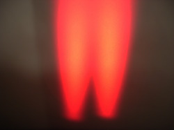
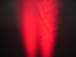
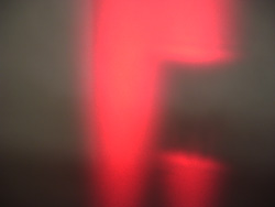
Step 5: Next check if the lasers are dirty. Open the "Diagnostic" instrument and in the "Command (Hex)" box type "ffff". Now hit "Transmit". Both lasers should be on. Point them at a white piece of paper. You should see a smooth red gradient. If not, refer to refer to the Laser Cleaning section of the BCAM repair manual.
 |
 |
 |
| Figure 2: This is how the lasers should look. | Figure 3: The laser on the right is dirty, if not cleaned it may not work properly. | Figure 4: The laser on the right is cracked, it must be replaced. |
Step 6: Also check that the laser are the proper intensity. After practice this can be done with the naked eye, but at first use a laser power meter. Each laser should be between 0.1 mW and 4.0 mW. Also the spread between the lasers should be less than a multiple of two. If the laser fail either test, refer to the Laser Power section of the BCAM Repair manual
Step 7: Epoxy the lasers of the A2049 board into the BCAM chassis using a low viscosity potting epoxy adhesive, we use Resinlab EP965 Black. Place the epoxy in a syringe with a 20G×1.5-in needle tip. The sharp end of the needle can be clipped to provide a flat surface to facilitate even application of the epoxy. Use a metal file to make a cut in the needle, clippers will pinch the opening. To save epoxy, you can mix the epoxy inside the syringe using a popsicle stick. Black epoxy is nice because you can easily see if any drips in front of the lens aperture. Generous amount of the epoxy must be evenly applied around the laser diodes housing. This will secure the lasers in place and isolate it electrically from the chassis. Once glued, the chassis must be left untouched for 24 hours on an even surface in a vertical position (laser holes facing the surface) in order to allow the epoxy to properly set.
Step 8: Using a ohmmeter, test the lasers for electrical continuity. The resistance between the laser diode and the chassis should be greater than 1 Megaohm. To do the test, set the ohmmeter to Audio Beep Mode. Insert one probe into one of the side holes the lid will be screwed into and keep it there for the whole test. When you insert the second probe into another screw hole, you should hear a beep. You may also hear a beep when you touch any screw in the BCAM. Now, run the probe around the rim of the lasers and on the laser pins, you should not hear anything. If you hear a beep then there is an abrasion in the chassis's anodizing and the test has failed. If there is no beep, reinsert the second probe into one of the side screw holes and listen for a beep, this confirms that the first probe had not slipped out of place. If the test fails, refer to the Laser Continuity section of the BCAM Repair manual. A slight abrasions -- sometimes noticeable by the naked eye, sometimes not -- in the anodizing of the chassis will eventually cause the BCAM to fail in the field.
Step 9: Prepare to glue the 6-mm lens into the brass lens holder. First, you must find the proper orientation of the 6-mm lens. The lens has a flat side and a convex side. Hold the lens under a light fixture. The flat side, if looked at closely, will show a small coherent sized reflection of the light fixture and a reflection of an immensely magnified light fixture. The convex side will have a larger coherent reflection and a smaller, in comparison to the flat surface, magnified reflection of the image. We want the flat side, the side with the immensely magnified reflection, to be facing up.
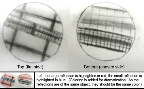
Step 10: Now that you have found the flat side of the lens, you are ready to epoxy it into the lens holder. Using the same epoxy as in Step 4 and a syringe, place three tiny drops of epoxy on the lens holder. Then place the 6-mm lens, flat side up, into the holder. Allow to dry for 24hrs.
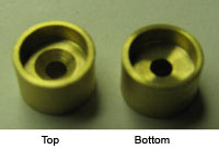
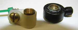
Step 11: After waiting 24hrs for the epoxy to dry, the lens holder is ready to be glued to the chassis. Spread the same epoxy adhesive around the lens hole and slide the lens holder in. While sliding, slowly rotate the lens holder to spread out the epoxy. The lens holder should sit 1.2mm from the front surface of the chassis. This depth gives the BCAM a focal range of 3 m. Do not install the lens holder flush with the front surface of the BCAM, because the focal range will be 1.5 m, and the BCAM will not perform well at long ranges. Creating a custom tool, with a washer clamped 1.2mm from the end of a spare lens holder, will make placing your lens at the correct depth much easier, see image below. For more on lens position, see the User Manual.
Step 12: Screw the A2016 board to the chassis, through the standoffs, using two of M2.5 × 8-mm screws.
Step 13:Place gaffer tape over holes on bottom of the chassis and on the top of the chassis's lid to prevent dust from entering. Gaffer tape is best because it will not leave a messy residue like electrical tape. Using a tank of compressed Nitrogen, thoroughly blow out any dust from inside the BCAM chassis. Also blow out any dust from the BCAM lid. A small "duster" can will not be powerful enough to get the BCAM reliable clean. Once you have blow out any dust, take the clear protective film off the CCD.
Step 14: Temporarily install the A2048 board connect the flex cables to the A2049 and A2016 boards, but do not screw the A2048 down yet. Close the lid.
Step 15: Let the BCAM sit for at least a day so that any dirt inside will settle.
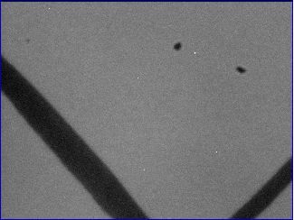
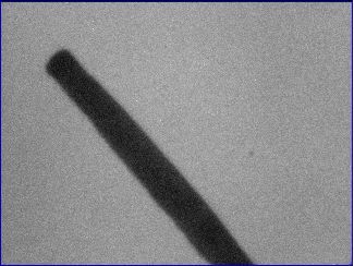
Step 16: Now check to see if there is any dirt on the CCD. Using the LWDAQ program, under the "Instrument" menu, run the "BCAM" instrument. Set "daq_source_element" to "3 4" with "daq_flash_seconds" set to "0.1" seconds, this will tell both lasers to flash. While the BCAM is capturing images, set a white paper in its field of vision with a dark hash mark across it. Dirt on the CCD is easy to spot. Below are a few examples of a clean and a dirty image. If the image shows signs of dirt, refer to the CCD Cleaning section of the BCAM repair manual.
 |
 |
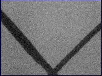 |
| Figure 7: This is a dirty image. (The dark line is part of the hash mark and is not dirt.) | Figure 8: This image is slightly dirty, but can pass as a clean image. | Figure 9: This is a perfectly clean image. |
Step 17: If the image is clean and both lasers flash, open the lid and screw down the A2048 board with 2 of M2.5 × 8-mm screws. Then close the lid and screw it down using 2 of M2.5 × 8-mm screws.
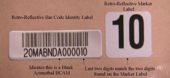
Step 18: Apply the retro-reflective bar code identity label on the lid and the matching two digit retro reflective marker label on the front surface of the BCAM chassis. An explanation of the identity labels is described in the last section of the manual, Identifier Labels.
Congratulations! You have competed the BCAM assembly procedure, the next process is to calibrate the cameras and lasers on each BCAM. For more information on calibrations, see BCAM Calibration.
Step 1: Begin by preparing the A2051 (main) board. Solder on a right angled RJ-45 adapter and two 12-way flex connectors. If the 12-way flex connectors only have one row of contacts, then position the contacts so they are facing inwards -- this is to insure alignment with the corresponding 12-way flex connector on the A2040 (side) board.
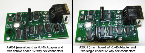
Step 2: Prepare the chassis: Place gaffer tape over holes on bottom of the chassis and on the top of the chassis's lid to prevent dust from entering. If it is a single ended BCAM, place tape over the back lens and laser holes. Gaffer tape is best because it will not leave a messy residue like electrical tape. Using a tank of compressed Nitrogen, thoroughly blow out any dust from inside the BCAM chassis. Also blow out any dust from the BCAM lid. A small "duster" can will not be powerful enough to get the BCAM reliable clean.
Step 3: The A2051 (main) board can now be screwed into the BCAM chassis using four of M2.5 × 8-mm screws.
Step 4: Now, determine the correct kind of A2040 (side) boards to use, each BCAM will require two. The double ended BCAMs will require two identical boards with all the components on both. A single ended BCAM will have different front facing and rear facing board; the front facing board requires the 12-way flex connector, the lasers with all the components required by the lasers, but no CCD; the rear facing A2040 board will only require the 12-way flex connector and a CCD, no other components or lasers. The differences are depicted below.
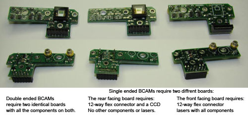
Step 5: Now that you have two A2040 (side) boards picked out, solder on a 12-way flex connectors to each board. If the 12-way flex connectors only have one row of contacts, then position the contacts so they are facing down -- this is to insure alignment with the corresponding 12-way flex connector on the A2051 (main) board.

Step 6: Solder on the CCD(s), be sure that the back of the CCD is flush against the board. Try to keep the clear protective film in place, you will be grateful later if you do not have to clean the surface of the CCD. Connect the 12-way flex cables -- do this now, because it will be more difficult once the board is screwed into place. Then, slide the laser diodes on, they will be soldered into place on Step 8.
Note: If you plan on using the older model TC255 CCD and not the newer TC255P CCD, please see TC255 Modification for directions.
Step 7: Place three standoffs on the chassis. The A2040 (side) board is then screwed to the chassis using three of M2.5 × 8-mm screws. There is a significant amount of wiggle room between the three screws and the screw holes, so it is important to note two things: First, insure that the lasers are not at a slight angle to the chassis and that the gold rim of the laser lies flush to the chassis without having to force the laser down into position. Second, make sure the standoff closest to the edge of the chassis is not sticking out slightly, this will interfere with the chassis lid closing smoothly. If you are using recycled parts, be careful when using the older zinc-plated standoffs, their height might vary slightly, but significantly, from each other or from the newer aluminum standoffs. You can spot the zinc-plated standoffs because they have a mat finish while the aluminum ones are shinny.
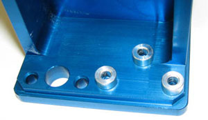
Step 8: Connect the flex connectors from the A2040 (side) boards to the A2051 (main) board.
Step 9: Ensuring that the gold rim of the laser lies flush to the chassis and that the laser is not at an angle, solder each lasers in place. Because it is a little difficult to de-solder the lasers once they are connected, you may want to test the setup with the LWDAQ BCAM tool before the lasers are soldered in place. This will require wiggling the laser with your finger to get all three prongs to connect.
Step 10: Next check if the lasers are dirty. Open the "BCAM" instrument and set "daq_source_element" to "1 2 3 4". Open the "Diagnostic" instrument and in the "Command (Hex)" box type "ffff". Now hit "Transmit". All four lasers should be on. Point them at a white piece of paper. You should see a smooth red gradient. If not, refer to refer to the Laser Cleaning section of the BCAM repair manual.
 |
 |
 |
| Figure 14: This is how the lasers should look. | Figure 15: The laser on the right is dirty, if not cleaned it may not work properly. | Figure 16: The laser on the right is cracked, it must be replaced. |
Step 11: Also check that the laser are the proper intensity. After practice this can be done with the naked eye, but at first use a laser power meter. Each laser should be between 0.01mW and 4.0mW. Also the spread between the lasers should be less than a multiple of two. If the laser fail either test, refer to the Laser Power section of the BCAM Repair manual
Step 12: Using a ohmmeter, test the lasers for electrical continuity. The resistance between the laser diode and the chassis shou1d be greater than 1 Megaohm. To do the test, set the ohmmeter to Audio Beep Mode. Insert one probe into one of the side holes the lid will be screwed into and keep it there for the whole test. When you insert the second probe into another screw hole, you should hear a beep. You may also hear a beep when you touch any screw in the BCAM. Now, run the probe around the rim of the lasers and on the laser pins, you should not hear anything. If you hear a beep then there is an abrasion in the chassis's anodizing and the test has failed. If there is no beep, reinsert the second probe into one of the side screw holes and listen for a beep, this confirms that the first probe had not slipped out of place. If the test fails, refer to the Laser Continuity section of the BCAM Repair manual. A slight abrasions -- sometimes noticeable by the naked eye, sometimes not -- in the anodizing of the chassis will eventually cause the BCAM to fail in the field.
Step 13: Prepare to glue the 6-mm lens into the brass lens holder. First, you must find the proper orientation of the 6-mm lens. The lens has a flat side and a convex side. Hold the lens under a light fixture. The flat side, if looked at closely, will show a small coherent sized reflection of the light fixture and a reflection of an immensely magnified light fixture. The convex side will have a larger coherent reflection and a smaller, in comparison to the flat surface, magnified reflection of the image. We want the flat side, the side with the immensely magnified reflection, to be facing up.

Step 14: Now that you have found the flat side of the lens, you are ready to epoxy it into the lens holder. Squeeze a low viscosity potting epoxy adhesive, we use Resinlab EP965 Black, into a syringe. To save epoxy, you can mix the epoxy inside the syringe using a popsicle stick. Black epoxy is nice because you can easily see if any drips in front of the lens aperture. Attach a 1.5-in needle tip to the syringe. The sharp end of the needle can be clipped to provide a flat surface to facilitate even application of the epoxy. Use a metal file to make a cut in the needle, clippers will pinch the opening. Using the syringe, place three tiny drops of epoxy on the lens holder. Then place the 6-mm lens, flat side up, into the holder. Allow to dry for 24hrs.

Step 15: After waiting 24hrs for the epoxy to dry, the lens holder is ready to be glued to the chassis. Spread the same epoxy adhesive around the lens hole and slide the lens holder in. While sliding, slowly rotate the lens holder to spread out the epoxy. The lens holder should sit 1.2mm from the front surface of the chassis. This depth gives the BCAM a focal range of 3 m. Do not install the lens holder flush with the front surface of the BCAM, because the focal range will be 1.5 m, and the BCAM will not perform well at long ranges. Creating a custom tool, with a washer clamped 1.2mm from the end of a spare lens holder, will make placing your lens at the correct depth much easier, see image below. For more on lens position, see here.

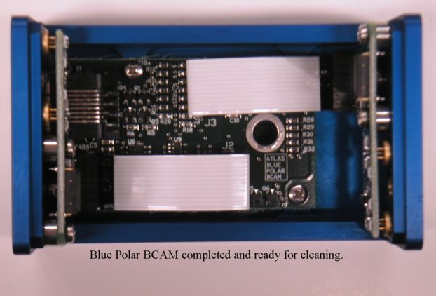
Step 16: Again, using a tank of compressed Nitrogen, thoroughly blow out any dust from inside the assembled BCAM and the BCAM lid. Once you have blow out any dust, take the clear protective film off the CCD(s) and close the lid. Let the BCAM sit for at least a day, so any dust inside will settle.
Step 17:Now check to see if there is any dirt on the CCD. Using the LWDAQ program, under the "Instrument" menu, run the "BCAM" instrument. Set "daq_source_element" to "1 2 3 4" with "daq_flash_seconds" set to "0.1" seconds, this will tell all lasers to flash. While the BCAM is capturing images, set a white paper in its field of vision with a dark hash mark across it. It will be apparent if the CCD's lens is clean. Below are a few examples of a clean and a dirty image. If you are testing a double ended BCAM, repeat this test with the rear facing CCD by setting "daq_device_element" to "1". If the image shows signs of dirt, refer to the CCD Cleaning section of the BCAM repair manual.
 |
 |
 |
| Figure 21: This is a dirty image. (The dark line is part of the hash mark and is not dirt.) | Figure 22: This image is slightly dirty, but can pass as a clean image. | Figure 23: This is a perfectly clean image. |
Step 18: If the image is clean and all four lasers flash, screw down the lid of the BCAM using 4 of M2.5 × 8-mm screws.
Step 19: Apply the retro-reflective bar code identity label on the lid and the matching two digit retro reflective marker label on the front surface of the BCAM chassis. An explanation of the identity labels is described in the next section of this manual, Identifier Labels. To distinguish double ended BCAMs, use a paint marker to make a colored dot between the three screw holes on the front of all double ended BCAMs.
Congratulations! You have competed the BCAM assembly procedure, the next process is to calibrate the cameras and lasers on each BCAM. For more information on calibrations, see BCAM Calibration.
A brief description of how to assemble sources for the Saloon Door Source Plates.

Each Source Requires:
Step 1: Assemble the A2049 board by soldering on a locking 6-way flex connector.
Step 2: R5 and R11 should both be 33k, place a blue dot on the board to mark that they are.
Step 3: Insert one side of the lasers into the A2049 and the other into the source plate.
Step 4: Place one washer between the plate and the PCB, place the other washer above the PCB. Screw the device together.
Step 5: Solder the lasers to the A2049 and clip the laser's leads short.
Step 6: Using an ohmmeter, test for a a connection between the screw and the the lasers. If there is a connection, you must discard the source plate.
Step 7: Use potting epoxy to permanently secure the position of the lasers.
Step 8: Store in a box, not a plastic bag where the plates can bang against the PCBs.
Below is a list of letter-assignments for ATLAS BCAM serial numbers. The full label has format 20MABNDxyyyyyy and the short label has format xyyyy, where x is a letter as shown below:
A Black Azimuthal BCAM (long)
B Blue Azimuthal BCAM (long)
L Black Polar BCAM (long)
M Blue Polar BCAM (long)
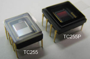
The older model TC255 is 0.3 inches wide, while the TC255P, which the BCAM side boards are designed for, is 04. inches wide. With this modification, however, in less than two minutes you can adapt the TC255 to fit the A2040. If this modification is preformed correctly, there is no significant difference between BCAMs made with the TC255 and the TC255P.
The only additional part required for this modification is a row of strip socks, Digi-Key Part Number ED7064. This model strip sock works best because the pins are the correct diameter to compensate for size difference between the TC255 and the TC255P.
Step 1: Using pliers, bend the pins of the TC255 outwards so that CCD and the pins lay flush to your desk. You may want to push down with your thumb to get all the pins completely flat. We find this to be the most time consuming part of the modification. Once the CCD and pins are flush, straighten out any pins that are angled, so that all the pins are parallel to each other.
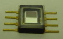

Step 2: Now, clip the pins so that they are 2 - 3 mm long.
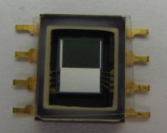
Step 3: Take your strip sock and snip off two 4-pin-long sections. Now, insert those sections through the back side of the A2040 -- the side of the board that has "A2040" stamped on it.
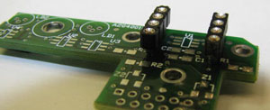
Step 4: Using extra strip socks, cross brace the strip socks you just inserted by building an interlocking log cabin shape. The temporary cross braces make the next steps much easier and will be removed later. Flip the setup over to reveal where the TC255 will be soldered to.

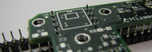
Step 5: Place the TC255 on the A2040 board so that each gold pin of the TC255 is directly below its corresponding silver strip sock pin. The 2 - 7 pins of TC255 has small indentations in them that the strip sock pins should fit into perfectly. The 1 and 8 pins of the TC255 have indentations, but the indentations do not line up with the strip sock pins. If the 1 and 8 pins' indentations do line up, then the TC255 is positioned incorrectly. Now, check that the TC255 lays completely flush to the A2040 and that each gold pin touches a silver pin, if not, the TC255 pins must be adjusted with pliers.
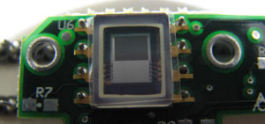
Step 6: With one drop of solder connect the 5 pin of the TC255 to the strip sock and the A2040. Check to make sure the TC255 still lays flush and that it is still square. Now, solder the remaining pins.
Step 7: Flip the setup over and remove the cross braces. Clip off the socket part of the strip socks so that what is left of the strip sock is almost flush with back of the A2040. On each pin, apply a drop of solder where you made the clip and you are done.

Since we first started making BCAMs we have made a few modifications to the Assembly Manual. If you are working with older and newer BCAMs that are slightly different, we thought you might want to know why. These lessons learned may also be applicable to your future projects. Below, are a few of the changes and why they were made