This manual describes how to fix some common BCAM problems. We invite you to read our BCAM User Manual and our BCAM Assembly Manual before moving on to reading the repair procedures.
The internal components of the BCAM are fairly rugged and you should not be afraid to open up the chassis to take a look if a BCAM stops working. As long as the BCAM is unplugged from the ethernet cable, you will not damage any inside component simply by touching it. The only components that you have to be careful about touching are the glass windows at the front of the laser diodes. The widows are normally protected because they are imbedded in the chassis, but if you poke at them with a probe, they can break.
One things to remember when you open a BCAM is that if the CCD gets dirty, you will have to clean it, a process that take a few minutes. Please refer to Cleaning.
Repair Materials:Certain repairs do not require recalibrating the BCAM. Cleaning the CCD or replacing the main board are two examples.
You will nullify the existing calibration data for that BCAM, however, if you unscrew a side board with a CCD or laser diode on it, or knock out an epoxied laser. A BCAM that undergoes such repairs will still function -- it can flash its lasers and take pictures -- but you may not be able to interpret the data it records without an updated calibration file.
Calibrating BCAMs requires special equipment. Before you begin a repair, be sure that either you can re-calibrate the BCAM once finished or that you do not need calibration data for the task you plan to use the BCAM for. You can read more about calibration at the BCAM Home Page or the BCAM User Manual
There are three boards and two flex cables inside every BCAM. For a more detailed explanation please see out BCAM User Manual and our BCAM Assembly Manual. Many repairs will require figuring out which one of the three boards is broken, removing it, and replacing it with a new board. There is no easy way to know which board is broken other than trial an error.
Step 1: Figure out why the BCAM ended up in the "broken" pile. If there is a note on the BCAM about how it failed, see if you can repeat that failure.
Step 1a: Test the lasers (a.k.a. elements): Using the LWDAQ program, run the BCAM instrument under the instrument menu. Allow all lasers to flash, set "daq_source_element" to "1 2 3 4" with "daq_flash_seconds" set to "0.1" seconds. Some BCAMs have two lasers and some BCAMs have four lasers, either way all should now be flashing in sequence, one after the other. If the lasers are all flashing, decrease the "daq_flash_seconds" to "0.000001" seconds. The lasers should flash very briefly now, so briefly that they will appear to be flashing at the same time.
Step 1b: Test the CCD(s): Still using the BCAM instrument in the LWDAQ program, return the "daq_flash_seconds" value to "0.1" seconds. Place the BCAM on a flat surface and see if it produces an image. If you are testing a double ended BCAM, repeat this test with the rear facing CCD by setting "daq_device_element" to "1".
These two simple test will not reveal every problem that may arise with a BCAM, but should catch most. If you have not been able to spot a problem, you may want to try checking if the CCD is dirty, by skipping to Step 7 of the Cleaning section or checking for laser continuity, using Step 1 of the Lasers Continuity section.
Step 2: Assuming you have found a reproducible problem with the BCAM, it is now time for trial and error. Open up the BCAM by removing all the exterior screws. Do your best not to get dirt into the BCAM, because cleaning it later will take several minutes. If the flex cables look loose, wiggle them. You will not permanently damage anything inside the BCAM by either taking it out or by putting back in the wrong way. If you remove something and do not know how it goes back in, refer to the BCAM Assembly Manual. If a CCD or laser on only one side of the BCAM is failing, then is is most like that side board that it is broken , but this rule is not always true. If components on both side boards have problems, then it is probably, but not always, the main board that is broken. Remove a board and replace it with a working spare. (See Steps 2a and 2b for a more thorough explanation.) Reattach the flex cables and see if the problem is fixed. If the problem is not fixed, put the board you just took out back in and try replacing a different board with a working spare.
Step 2a: Removing boards held by screws: Most boards are held down by only screws. If you are picking a board to replace at random, we highly recommend testing the only screwed ones first.
Step 2b: Removing boards held by epoxy: All Azimuthal A2049 (side) boards with laser diodes are epoxied in place. Some Polar A2040 (side) boards with laser diode have the lasers epoxied in place in addition to the board being screwed down. You can tell if a Polar BCAMS lasers are epoxied in place because you will be able to see a bead of epoxy around each laser diode. To get the lasers and the board they are soldered onto out, on the outside of the chassis, insert a screwdriver into the laser hole and hit it with a hammer. This ungraceful approach, permanently damages the lasers, but it the only we we have found of getting the epoxied lasers out. Using a probe, gently scrap out any epoxy that remains in the laser hole. A very common problem that happens when lasers have to be knocked out in this manner is that the anodizing on the chassis will get scratched. Always check the replacement with the Lasers Continuity test. If the replacements fail the test, follow the instructions in the Lasers Continuity section.
Step 3: Once you have completed all repairs, run the dirty CCD test described in Step 7 of Cleaning. If applicable, re-calibrate the BCAM. Refer to Calibration for calibration details.
Problems may arise when there is "dirt" on the CCD, especially when the spec of dirt is in the viewing field. A demonstration of a common dirt related problem is shown in figure 1, where the unclean viewing camera acquires images of sources, which were placed on a stage and were moved in 10-micron intervals. The camera was separated 2.5 meters away from the sources. One of the sources is blocked due to the dirt that is obstructing light from entering the CCD, eventually the spot reappears.

The process of cleaning the CCD usually takes about five minutes. If you are not sure whether your BCAM needs to be cleaned, please skip ahead to Step 7.
Step 1: If you are cleaning a Polar BCAM, move on to Step 2. If you are cleaning a Azimuthal BCAM, you must unscrew the A2048 (main) board and detach the flex cables to gain access to the CCD underneath.
Step 2: Using a tank of compressed Nitrogen, thoroughly blow out any dust from inside the assembled BCAM. A small "duster" can will not be powerful enough to get the BCAM reliable clean.
Step 3: If you have not done so already, remove the plastic protective film found on the CCD.
Step 4: Spray anti-static foam glass cleaner into a container and dab a folded sheet of optical lens tissue in it. Wipe the CCD's lens in one direction and never use the same spot of the lens tissue for more than one pass; the tissue will be just as likely to deposit the dirt back onto the lens as it was to pick it up in the first place.
Step 5: Under a bright light examine the surface of the lens; if a dust particle is visible wipe it off with the lens tissue. Repeat this process until clean.
Step 6: Close the lid of the BCAM. If you are cleaning an Azimuthal BCAM, put the A2048 (main) board back in place and reconnect the flex cables. You may want to wait to screw the the A2048 down until the BCAM passes the test in Step 7.
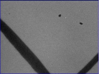
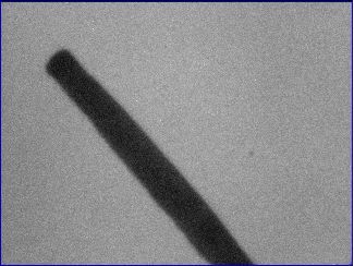
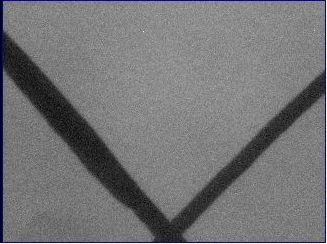
Step 7: Now check to see if there is any dirt on the CCD. Using the LWDAQ program, run the BCAM instrument under the instrument menu. Allow all lasers to flash, set "daq_source_element" to "1 2 3 4" with "daq_flash_seconds" set to "0.1" seconds. While the BCAM is capturing images, set a white paper in its field of vision with a dark hash mark across it. It will be apparent if the CCD's lens is clean. Below are a few examples of a clean and a dirty image. If you are testing a double ended BCAM, repeat this test with the rear facing CCD by setting "daq_device_element" to "1". If the image shows signs of dirt, wipe it again with the lens cleaner.
 |
 |
 |
| Figure 2: This is a dirty image. (The dark line is part of the hash mark and is not dirt.) | Figure 3: This image is slightly dirty, but can pass as a clean image. | Figure 4: This is a perfectly clean image. |
Step 7: If the image is clean, screw down the lid of the BCAM using M2.5 × 8-mm screws.
Dirt on a laser will not effect BCAM operation most of the time, but may prevent the BCAM from working at specific angles or distances. Therefore dirty lasers should be cleaned. Cleaning lasers is tedious and difficult. It is hard to remove dirt and the lens the dirt rests on is very fragile. Applying too much pressure while cleaning will crack the laser's lens. While checking to see if a laser is dirty or while cleaning it, you may find a laser with a cracked lens. Cracked lasers must be replaced.
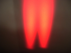
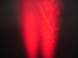
Step 1: Check if the lasers are dirty. Open the "BCAM" instrument and set "daq_source_element" to "1 2 3 4". Open the "Diagnostic" instrument and in the "Command (Hex)" box type "ffff". Now hit "Transmit". All four lasers should be on. Point them at a white piece of paper. You should see a smooth red gradient. If not, follow the steps below..
 |
 |
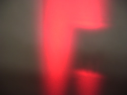 |
| Figure 14: This is how the lasers should look. | Figure 15: The laser on the right is dirty, if not cleaned it may not work properly. | Figure 16: The laser on the right is cracked, it must be replaced. |
Step 2: Keep the laser powered on, so that yo can watch your progress. With a metal probe gently push on the dirt. You should see the dirt move around. Do not push too hard, the laser's lens will crack. If the dirt does not move, you may have a cracked laser.
Step 3: As the probe picks up the dirt, wipe the probe only wiht anti-static paper.
Check that the laser are the proper intensity. After practice this can be done with the naked eye, but at first use a laser power meter. Each laser should be between 0.01mW and 4.0mW. Also the spread between the lasers should be less than a multiple of two. If the laser fail either test, something must be fixed.
If a laser's power is greater the 4.0mw, the most likely problem is that R5 or R11 are not 33k resistors. Many of early BCAMs have this problem.
If one, or both, lasers are dimmer than .01mW, the cause is most likely a soldering problem. While one may suspect a poor solder joint to cause the laser to not work at all, often is causes a very dim laser.
Broken lasers are rare, but do happen. If nothing else fixes the problem, that may be it.
A slight abrasions in the anodizing of the chassis -- sometimes noticeable by the naked eye, sometimes not --will eventually cause the BCAM to fail in the field. This problem is difficult to diagnose, because the BCAM failure is not always reproducible.
Step 1: Using a ohmmeter, test the lasers for electrical continuity. The resistance between the laser diode and the chassis shou1d be greater than 1 Megaohm. To do the test, set the ohmmeter to Audio Beep Mode. Insert one probe into one of the side holes the lid will be screwed into and keep it there for the whole test. When you insert the second probe into another screw hole, you should hear a beep. You may also hear a beep when you touch any screw in the BCAM. Now, run the probe around the rim of the lasers and on the laser pins, you should not hear anything. If you hear a beep then there is an abrasion in the chassis's anodizing and the test has failed. If there is no beep, reinsert the second probe into one of the side screw holes and listen for a beep, this confirms that the first probe had not slipped out of place.
Step 2: Remove the side board with the failed lasers. If the lasers are epoxied in place, insert a screwdriver into the laser hole on the outside of the chassis and hit it with a hammer. This ungraceful approach, permanently damages the lasers, but it the only we we have found of getting the lasers out. Using a probe, gently scrap out any epoxy that remains in the laser hole.
Step 3: With the board detached from the chassis, use the LWDAQ program to test the lasers. Run the BCAM instrument under the instrument menu. Allow all lasers to flash, set "daq_source_element" to "1 2 3 4" with "daq_flash_seconds" set to "0.1" seconds. If the lasers are all flashing, decrease the "daq_flash_seconds" to "0.000001" seconds. The lasers should flash very briefly now, so briefly that they will appear to be flashing at the same time. If the laser are broken, replace them before moving on to Step 4.
Step 4: Inspect the chassis and look for any scratches in the anodizing. If you see a scratch around the laser hole's rim, but not in hole itself, or if you don't see any scratches at all, skip Step 5a and proceed to Step 5b. If you see a scratch in the hole or if you are working with an Azimuthal BCAM (where the lasers must be epoxied back in place), then complete steps 5a and 5b.
Step 5a: Wrap the laser once around in 850 Polyester Film Tape, McMaster-Carr part number 75895A26. We use this tape because it is very thin and very strong. Cut a generous piece of tape and position its bottom edge on the rim of the laser. Using tweezers, wrap the tape around the laser. Use a pair of small scissors to cut away excess tape. Move on to Step 5b.
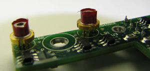
Step 5b: Place a Kapton Washer, McMaster-Carr part number 91435, around the laser. Clip the washer down so it does not cover the lens aperture or prevent the BCAM lid from closing.
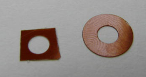
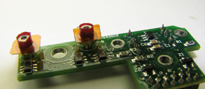
Step 6: If the taped laser does not fit back into the chassis's laser holes, you will have to drill out the hole. The taped laser should fit into newer revision Polar BCAMs, older revisions Polar BCAMs and Azimuthal BCAMs will probably have to be drilled. Clamp the BCAM in place on a drill press. Using a 5/32 inch bit, enlarge the laser holes.
Step 7: Screw the side board into the chassis. If it is an Azimuthal BCAM, press the board in, but do not epoxy it yet.
Step 8: Repeating Step 1, test the lasers for electrical continuity. If the test fails, go back and complete Step 5a, if you have not already.
Step 9: If it is an Azimuthal BCAM, you may now epoxy the laser into place. If it is a Polar BCAM, you do not need to use epoxy, even if the lasers were originally epoxied in place.
Step 10: If you drilled out the laser holes you must test to see if either hole accidentally creates a third light source by reflecting the laser light. This happens occasionally when there is groove in the laser hole that catches light. If you did not drill out the holes continue to Step 11. Point a second BCAM at the repaired BCAM. Using the LWDAQ BCAM instrument allow all lasers to flash on the repaired BCAM and turn on the CCD on the second BCAM. Capture images at different distances and with "daq_flash_seconds" set to several different levels. You should see only two points of light. If you see a third point of light, then a hole has to be re-drilled. If the side board is screwed in, unscrew it. If the side board is epoxied on, you can attempt to smooth out the hole with the drill press while the lasers are still epoxied in place.
Step 11: Run the dirty CCD test described in Step 7 of Cleaning. Then, re-calibrate the BCAM. Refer to Calibration for calibration details.
