| Schematic | PCB | Assembly |
The Polar BCAM Head (A2051) is a Long-Wire Data Acquisition (LWDAQ) Device that reads out two TC255P image sensors and drives four light sources. When the A2051 is connected to a pair of Polar BCAM Side Heads (A2040), as shown below, these light sources are laser diodes (LDP65001E or equivalent). A BCAM is an optical surveying instrument (Brandeis CCD Angle Monitor).

The Black and Blue Polar BCAMs each use one Polar BCAM Head. The Black BCAM is part number P-BCAM-L, where the "L" is for "left-handed". The Blue BCAM is P-BCAM-R, where the "R" is for "right-handed".

By default, the device is equipped with two cameras and four lasers, so it is "double-ended". We have made versions that have only a single camera, facing either forward or backward. These are the P-BCAM-LSF, for "left-handed single front-side camera", P-BCAM-RSR, for "right-handed single rear-side camera" and so on.
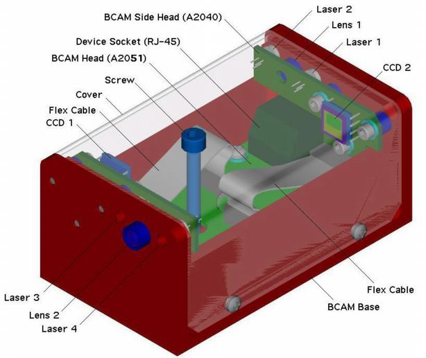
In a double-ended BCAM, the A2051 works with two BCAM Side Heads A2040s to drive two TC255P image sensors and four laser diode light sources. In a single-ended BCAM, the A2051 needs two A2040s, but only one image sensor and two lasers are present on the A2040s.
| Version | Description |
|---|---|
| C | Camera Head (A2051L modified for TC237 readout, no lasers) |
| F | Fiber Illuminator (A2051L with laser circuits only, two-pin headers) |
| L | Black Polar BCAM Head (mirror image of A2051R) |
| Q | Quad LED Head (A2051S with pigtails and LEDs) |
| R | Blue Polar BCAM Head (mirror image of A2051L) |
| S | Azimuthal Source Head (A2051L with laser circuits only) |
| W | WPS Head |
The A2051L is designed to operate with the Black Polar BCAM Side Head (A2040L). The A2051R is designed to operate with the Blue Polar BCAM Side Head (A2040R).

The A2051S has six-way zero-insertion force flex connectors in place of twelve-way low-insertin force flex connectors, and operates either with the Black Azimuthal BCAM Side Head (A2049L) or Blue Azimuthal BCAM Side Head (A2049R). It also omits all parts in the A2051 circuit that are necessary only for CCD readout. The footprints for these parts on the circuit board are present but empty.
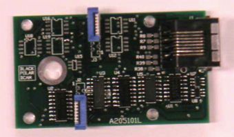
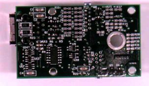
The A2051S operates with two Azimuthal Source Heads (A2049), either a pair of A2049M mounted on black plates, or two A2049N mounted on blue plates, to make an Azimuthal Source Plate, also known as a Saloon Door Source, as used in the ATLAS end-cap alignment system.

The A2051Q is an A2051S without the flex connectors. Instead, we solder four twisted pairs of wire into the flex connector footprints. Each twisted pair provides a single high-power LED for connection to an optical fiber. There is a resistor in series with the LED acting to control the LED current. The twisted pairs receive 15 V running through two 47-Ω, 0.5-W resistors on the A2051Q board. Thus connecting a diode without a resistor would allow 150 mA to flow through the diode. Additional resistance reduces the current.
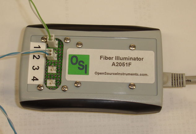
The A2051F is an A2051S in which the flex connectors for lasers have been replaced by four short twisted-pair cables running to four two-pin 0.1" headers. We can connect fiber-coupled LEDs or lasers with laser drivers directly to these two-pin headers and switch them on and off using the A2051F. Thus the A2051F is the same as an A2051Q with the wires cut near the circuit board and terminated with two-pin headers. For mechanical strength, we mount the two-pin headers on a circuit board of their own, and enclose this and the main circuit board in a plastic box.
The A2051W has eight-way flex connectors occupying pins 1-8 of J2 and J3. These connect to two TC255P Minimal Heads (A2016P) via two 8-way flex cables. In the place of pins 11 and 12 of J3, we solder a pair of wires with a two-way 0.1" socket on the end.We modify the A2051 circuit by placing R23 and R24 in parallel instead of in series. We solder the two resistors on top of one another and short the empty footprint with a piece of wire. Now we can connect the two-way socket to a Nine-LED Array (A2041W). The 22 Ω parallel resistance of R23 and R24 allows roughly 80 mA to flow into the LED array when we connect 15 V across the combination. For a photograph of the A2051W and A2041W installed in a Wire Position Sensor, see here.
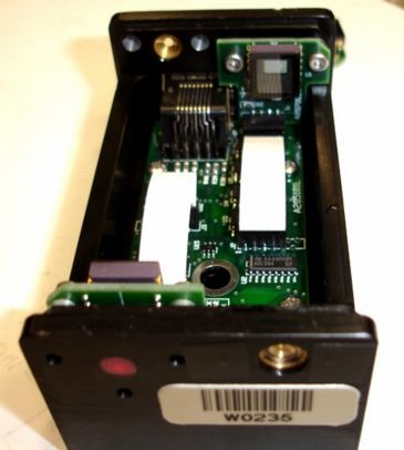
The A2051C is similar to the A2051W. It is designed to work with one or two TC237B Minimal Heads (A2070). The board provides two eight-way flex connectors for the connection to the minimal heads. We change R29 and R35 to 3.3 kΩ in order to increase the gain of the output amplifier to account for the lower output of the TC237B sensor. Lasers or LEDs can be powered using pins 10 and 12 of both the J2 and J3 footprints.
All versions of the A2051 connect to a LWDAQ driver (such as the A2037) or multiplexer (such as the A2046) with a LWDAQ cable. The A2051 is LWDAQ device type 2. The DAQ software selects a camera or laser diode in the BCAM by specifying a device element number to the driver. On flash jobs, elements one to four select lasers one to four. On image retrieval jobs, elements one and two select cameras one and two.
The A2051 complies with the LWDAQ Specification. It's LWDAQ Device type is 2 (TC255P). Its laser drivers are elements 1 through 4, and its cameras are elements 1 and 2.
| DC16 | DC15 | DC14 | DC13 | DC12 | DC11 | DC10 | DC9 | DC8 | DC7 | DC6 | DC5 | DC4 | DC3 | DC2 | DC1 |
|---|---|---|---|---|---|---|---|---|---|---|---|---|---|---|---|
| X | X | X | ON4 | ON3 | ON2 | ON1 | CCD1 | WAKE | LB | ABEN | ABGD | IAGD | SAGD | SRGD | DCEN |
The signals acronyms are DCEN for direct clock enable, SRGD for serial register gate digital, SAGD for storage area gate digital, IAGD for image area gate digital, ABGD for anti-blooming gate digital, ABEN for anti-blooming enable, and LB for loop back.
The CCD1 bit, when asserted, selects the image sensor connected to J3, which is the rear-facing camera on a polar BCAM. We select the rear-facing camera by specifying device element 1 during image readout. When we specify device element 2 or 0, the CCD1 bit will be unasserted, and the image sensor connected to J2 will be selected. This sensor is the one used by the front-facing camera. By default, the device element number used by LWDAQ Drivers is 0, so by default, the rear-facing camera will be the one that gets read out.
Here is a diagram showing the names of the lasers and cameras in a Black Polar BCAM. The image sensorss and lasers share channel numbers. The driver knows that flash jobs are directed towards the lasers, and image retrieval jobs are directed towards the image sensors.
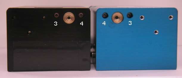
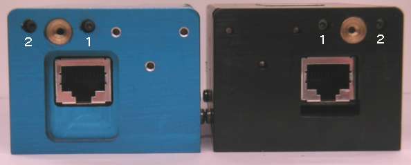
The Blue Polar BCAM is a mirror image of the Black Polar BCAM. Lasers 1 and 3 are to the right of lasers 2 and 4 respectively. This exchange of positions allows us to distinguish between black and blue polar BCAMs in our field of view.
The A2051, when combined with two Polar BCAM Side Heads (A2040), provides two TC255P image sensors and four laser diodes. Let us assume you have the A2051 in a polar BCAM enclosure, along with its A2040s. If the BCAM has lasers and lenses on both sides, you will be able to capture images from both TC255Ps, and flash all four of the lasers. If the BCAM has a lens only on the front side, which is the side opposite the connector, then you will be able to flash only the two lasers at the front, and capture images only from the image sensor at the back.
Once you are capturing images, you will need to adjust the exposure time until you get the image you want. If the exposure time is too long, the image will be white. If it is too short, it will be black. The black image from a working A2051 is, however, different from the black image from a broken A2051, or one that is not connected. Each driver introduces its own noise, but this will be less than the noise present in the black image from a working head.
If your A2051 is not mounted in a Polar BCAM enclosure, you will have to install it in such an enclosure and connect it to its two BCAM Side Heads (A2040). For these connections you need twelve-way 1-mm flex cables.
The A2051 provides exposure of the TC255P with and without anti-blooming, and drives four light sources. When connected to a pair of A2040s the A2051 drives four lasers and two TC255P image sensors.
When an image sensor pixel fills up with light-induced charge, the charge tends to flow into neighboring pixels and cause them to saturate as well. A bright spot in an image can turn into a large, bright smear, in a phenomenon called blooming. The TC255P image sensor provides an anti-blooming clock input that you can pulse during an exposure, and which gets rid of excess charge before it can spread into neighboring pixels. The anti-blooming process does, however, degrade the linearity of the pixel response. We do not use anti-blooming when we take BCAM images, and the LWDAQ Software's BCAM Instrument does not support anti-blooming. Nevertheless, when we take diagnostic images of the field of view of the BCAM, with exposure times of a few hundred milliseconds, anti-blooming makes sure that bright reflective objects, or overhead lights, do not flood the image. In such cases, we can use the Camera Instrument to obtain images from a BCAM. The Camera Instrument supports anti-blooming. We say more about anti-blooming, and provide some example images, in our Camera Head (A2056) Manual.
To expose the image sensor without anti-blooming, send the following instructions to the LWDAQ driver:
An anti-blooming exposure requires the following LWDAQ driver instructions:
To flash one of the A2051 lasers, send the following instructions to the LWDAQ driver:
To measure the propagation delay of signals traveling from the driver to the A2051 and back again, execute a loop job and read the loop time out of the driver. The A2051 is asleep when it powers up, and goes to sleep when you execute a sleep job.
You will find the above read-out sequences layed out in BCAM.tcl, the TclTk script that defines the BCAM Instrument in our LWDAQ Software.
See here for a discussion of the radiation tolerance of the A2047, which is a camera circuit very similar to the A2051.
The A2051 can turn on its lasers only if their metal cases are isolated from the BCAM chassis, as we describe in the A2049 Manual.
For a discussion of image geometry, and how to translate between points in the image sensor and points in the image on our computer screen, see the Image Geometry section of the TC255P Minimal Head (A2016) Manual. For instructions on finding Pin One on a TC255P, see the Pin One section of the same manual.
We discuss the image quality provided by our various TC255P readout circuits in the Image Contrast of the A2036 Manual.
We picked an A2051L at random and measured its power consumption in three states. The A2051L was connected to two fully-populated Black BCAM Side Heads (A2040L).
| State | +15 V | −15 V | +5 V |
|---|---|---|---|
| Asleep | 10 μA | 10 μA | 2.9 mA |
| Awake, no activity | 55 mA | 48 mA | 3.2 mA |
| Awake, 6 images/s | 55 mA | 48 mA | 3.4 mA |
| Awake, 1 laser on | 84 mA | 48 mA | 3.4 mA |
| Awake, 2 lasers on | 107 mA | 48 mA | 3.4 mA |
| Awake, 3 lasers on | 129 mA | 48 mA | 3.4 mA |
| Awake, 4 lasers on | 136 mA | 48 mA | 3.4 mA |
| Awake, 4 lasers on, −15V disconnected | 240 mA | 0 mA | 3.4 mA |
| Awake, any command, +15V disconnected | 0 mA | 0 mA | 0 mA |
Note: All our schematics and Gerber files are distributed under the GNU General Public License.