The Azimuthal BCAM Head (A2048) is a Long-Wire Data Acquisition (LWDAQ) Device that reads out one TC255P or TC237B image sensor and drives two light sources. When the A2048 is connected to an Azimuthal BCAM Side Head (A2049), these light sources are laser diodes (LDP65001E or equivalent). A BCAM is an optical survey instrument. The A2048 connects to a LWDAQ driver (such as the A2037) or multiplexer (such as the A2046) with a LWDAQ cable. The A2048 is designed for use with the Azimthal BCAM.

The Black Azzimuthal BCAM has part number A-BCAM-L, the L stands for "left-handed". The Blue Azimuthal BCAM is A-BCAM-R, where R stands for "right-handed".

The A2048L is designed to operate with the Black Azimuthal BCAM Side Head (A2049L) and the TC255P Minimal Head (A2016L) in a Black Azimuthal BCAM. The A2048R is designed to operate with the Blue Azimuthal BCAM Side Head (A2049R) and the TC255P Minimal Head (A2016R) in a Blue Azimuthal BCAM.
| Version | Description |
| C | Black Azimuthal BCAM Head for TC237B (mirror image of A2048D) |
| D | Blue Azimuthal BCAM Head for TC237B (mirror image of A2048C) |
| L | Black Azimuthal BCAM Head (mirror image of A2048R) |
| R | Blue Azimuthal BCAM Head (mirror image of A2048L) |
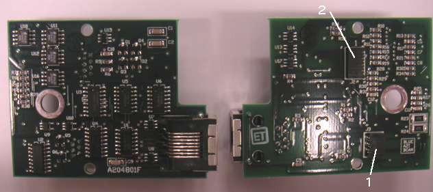
The Black and Blue Azimthal BCAM circuits are mirror images of one another. Each provides an eight-way socket for connection to the image sensor and a six-way socket for connection to the dual laser side-board.
The A2048C and A2048D are newer versions of the A2048 that work with the TC237B image sensor. While the A2048L and A2048R work with the TC255P Minimal Head (A2016L) and TC255P Minimal Head (A2016R) respectively, the A2048C and A2048D work with the TC237B Minimal Head (A2070L) and TC237B Minimal Head (A2070R) respectively. The TC237B circuits have R26 and R29 set to 3.3 kΩ in order to raise the gain of the circuit's output amplifier for the weaker TC237B output. Other than that, the two circuits are identical.
The A2048 complies with the LWDAQ Specification. It device type 2 (TC255P) for the purpose of device-dependent jobs. The lasers are elements 3 and 4, with 3 being the inner laser and 4 being the outer laser.
| DC16 | DC15 | DC14 | DC13 | DC12 | DC11 | DC10 | DC9 | DC8 | DC7 | DC6 | DC5 | DC4 | DC3 | DC2 | DC1 |
|---|---|---|---|---|---|---|---|---|---|---|---|---|---|---|---|
| X | X | X | ON4 | ON3 | X | X | X | WAKE | LB | ABEN | ABGD | IAGD | SAGD | SRGD | DCEN |
The figure below shows how the signals ON3 and ON4, which correspond to element numbers 3 and 4 during a flash job, correspond to the lasers on each type of Azimuthal BCAM.
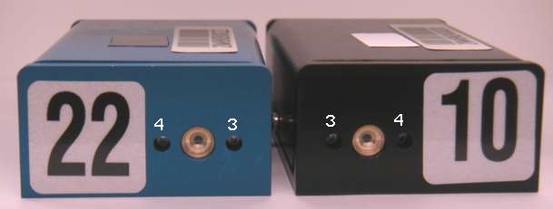
The Blue Azimuthal BCAM is a mirror image of the Black Azimuthal BCAM. Laser 3 is on the right when seen from the front, instead of on the right. This exchange of positions allows us to distinguish between black and blue azimuthal BCAMs in our field of view.
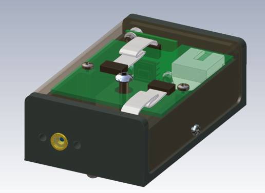
In operation, the A2048 is similar to the Polar BCAM Head (A2051). When connected to an Azimuthal BCAM Side Head (A2049) and TC255P Minimal Head (A2016), the A2048 provides light sources and image capture for an Azimuthal BCAM.
The A2048 provides image capture for the TC255P with and without anti-blooming. The TC237B image capture always provides a limited amount of anti-blooming. We discuss anti-blooming in the Anti-Blooming section of the Camera Head (A2056) Manual. When reading an image out of the A2048, we use the same steps presented in the Operation section of the Polar BCAM Head Manual. For more image acquisition details, see the Discussion section of the Inplane Sensor Head (A2036) Manual. You will find the data acquisition steps required to capture an image and flash lasers on an A2048 in BCAM.tcl, which is the TclTk script that defines the BCAM Instrument in our LWDAQ Software. In Driver.tcl you will find the routines that compose TCPIP messages to communicate with a LWDAQ Driver. We use these routines in BCAM.tcl.
The A2048 provides two laser-diode point sources. We flash these sources in the same way we flash the sources of a Polar BCAM Head (A2051 ).
See here for a discussion of the radiation tolerance of the A2047, which is a camera circuit very similar to the A2048.
The A2048 can turn on its lasers only if their metal cases are isolated from the BCAM chassis, as we describe in the A2049 Manual.
For a discussion of TC255P image geometry, and how to translate between points in the image sensor and points in the image on our computer screen, see the Image Geometry section of the TC255P Minimal Head (A2016) Manual. For instructions on finding Pin One on a TC255P, see the Pin One section of the same manual. The manual for the TC237B Minimal Head (A2070) presents the image gemoetry of the TC237B in detail.
We discuss the image quality provided by our various TC255P readout circuits in the Image Contrast of the A2036 Manual. The TC237B provides similar contrast when used with the A2048C or A2048D.
We picked an A2048L at random and measured its power consumption in three states. The A2048L was connected to an A2049L and an A2016L.
| State | +15 V | -15 V | +5 V | Total Power |
| Asleep | 10 μA | 10 μA | 2.9 mA | 14 mW |
| Awake (0 images/s) | 40 mA | 35 mA | 3.2 mA | 1.1 W |
| Awake (6 images/s) | 40 mA | 40 mA | 3.4 mA | 1.2 W |
| One Laser On | 70 mA | 40 mA | 3.4 mA | 1.6 W |
Note: All our schematics and Gerber files are distributed under the GNU General Public License.