The LWDAQ Ten-Slot Multiplexer (A2046) is a Long-Wire Data Acquisition multiplexer. The A2046 connects to a driver via a root cable and perhaps repeater. The root cable plugs into the A2046's root socket. The A2046 connects to up to ten devices via branch cables. The branch cables plug into the A2046's branch sockets.
The A2046 chassis is made of aluminum sheet with a conductive anodization. The A2046 circuit's 0-V supply is not connected directly to the chassis. The connection between the chassis ground and the A2046 0V is with a 100-nF capacitor.
| Version | Description |
| A2046A | LWDAQ Multiplexer in Enclosure |
The A2046 receives the LWDAQ transmit signal, T and re-transmits it to an array of ten analog switches. The incoming T is received by an LVDS receiver and re-transmitted by an LVDS transmitter. The analog switches determine which of the ten branch sockets receive T. The same analog switches determine which of ten branch sockets will provide the LWDAQ receive signal, R. The A2046 buffers R+ and R− with op-amps before they proceed up the root cable to the driver.
The A2046 is complies with the LWDAQ Specification. It provides the following address bit allocation.
| DA15 | DA14 | DA13 | DA12 | DA11 | DA10 | DA9 | DA8 | DA7 | DA6 | DA5 | DA4 | DA3 | DA2 | DA1 | DA0 |
|---|---|---|---|---|---|---|---|---|---|---|---|---|---|---|---|
| X | X | X | X | X | 10 | 9 | 8 | 7 | 6 | 5 | 4 | 3 | 2 | 1 | X |
Note that the A2046 ignores address bit zero (DA0). This allows a repeater to operate between a driver and the A2046, using DA0 to switch off power to the multiplexer.
The multiplexer connects to a LWDAQ Driver via its root socket, and to up to ten LWDAQ Devices via its branch sockets. All the multiplexer's power, and that of its devices, comes down the root cable from the driver. To direct device communication to a particular branch socket, the driver transmits a LWDAQ address word down the root cable, and this address word is received by the multiplexer and used to select one or more branch sockets. For an example of how a driver might be instructed to make such an address transmission, see the appropriate section of the LWDAQ Driver (A2037) manual. To select the device on socket n, you instruct your LWDAQ driver to transmit an address word with the nth bit set to 1, and all other bits set to zero. The address word that selects branch socket 3 is $0008 (hex 0008), and the word that selects branch socket 10 is $0400.
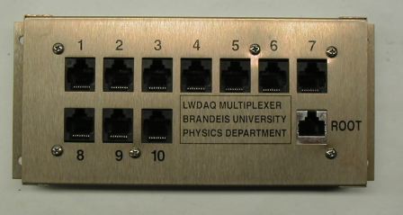
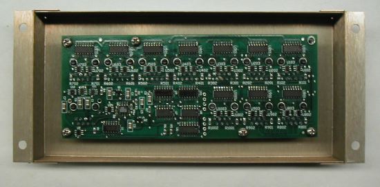
The A2046 is designed to mount onto a flat metal surface with four M6 mounting bolts that pass through the four holes in its mounting flanges. The figure above shows the enclosure and mounting flanges from above. The figure below shows the same enclosure from below. You will find a drawing of the enclosure here.
With the A2046 mounted on a plate, its electronics are enclosed in a faraday cage. All you have to do is connect the driver via a root cable to the socket marked "ROOT", and your devices to the sockets marked "1" through "10". The electronic 0-V supply is connected to the faraday cage through a 100-nF capacitor. There is no low-frequency connection between the faraday cage and the multiplexer circuit.
When we insert an A2046 in the signal path between a driver and a device, the device's loop time by roughly 25 ns. This 25 ns is the delay introduced by the two 60-MHz op-amps that buffer the R+ and R&minus: lines on their way back to the driver.
| State | +15 V | −15 V | +5 V |
|---|---|---|---|
| Any | 14 mA | 13 mA | 3.6 mA |
The A2046 does responds only to address words. It does not go to sleep. It's current consumption is dominated by that of its dual op-amp, which buffers R, and the LVDS transceiver, which re-transmits T. For details of how we switch from one multiplexer channel to another during data acquisition, consult Diagnostic.tcl, which defines procedures like LWDAQ_sleepall_Diagnostic. This procedure goes through all driver and multiplexer sockets of a LWDAQ system and sends all devices to sleep. It uses LWDAQ_set_driver_mux, which is defined in Driver.tcl. In Driver.tcl, you will see how to compose a TCPIP message for a LWDAQ Driver that will instruct the driver to select a particular multiplexer channel.
We subjected an A2046A to 100 krad of ionizing radiation at 20 krad/hr with power applied to the circuit. Five years after the irradiation, current consumption from the 3.3V supply is 32 mA. The 74VHC123 is not pulsing. When we replace it with a new chip, we find that the analog switches used throughout the multiplexer don't work. The switches are always closed. The remaining parts on the board appear to function properly. The failure of the A2046 is similar to that of the A2036, which uses the same analog switches. By examination of our radiation tolerance results for the A2036, we conclude that the radiation tolerance of the A2046 is at leat 20 krad.
[14-JAN-19] Of one thousand A2046A assemblies shipped to CERN, we have nine in a bin at Brandeis returned from CERN as being suspicious, unreliable, or outright broken. Of these, five work perfectly with a camera on all channels, three need U1 replaced, and one has a short circuit from DA to 0V that we don't bother to track down. When U1 needs replacing, 3V3 is low because U1 is drawing too much current. If we connect external 3.3 V, U1 gets hot.
The A2046 enclosure provides space for a cabeling diagram.
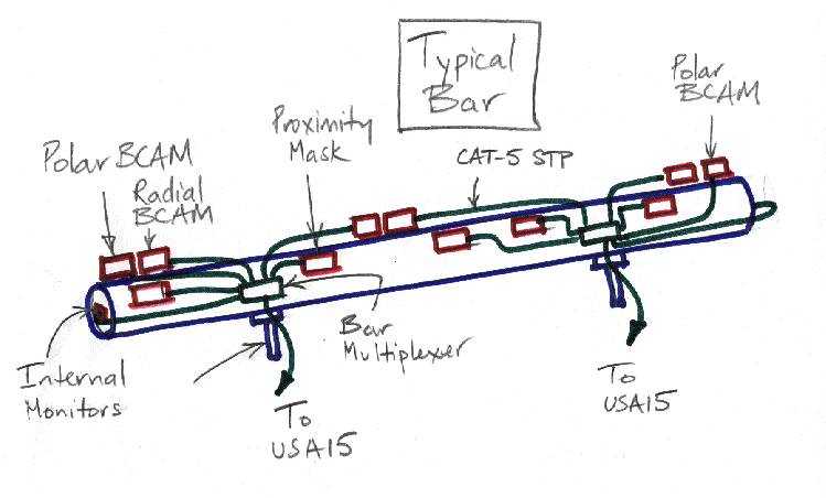
The figure shows the label we used in the ATLAS end-cap muon chamber multiplexers. You will find a hand-drawn diagram of the connections to a chamber multiplexer here and another drawing of the connections on an end-cap alignment bar here.
Here are the pages of the circuit diagram.
Page 1: LVD TransceiverHere are the available printed circuit board files.
A204601C for A2046A