The Nine-LED Array (A2041) consists of nine surface-mount LEDs in series. A two-pin header allows you to connect a constant-current source to the nine LEDs. In some versions, we have an additional visible LED in parallel with the main array of nine, so as to indicate that the array power is turned on.
The A2041A is as shown above. It is 31.25 mm square and provides footprints for nine HSDL-4400 infra-red LEDs.

The forward voltage drop of these nine LEDs at 80 mA forward current is roughly 13.5 V. Maximum recommended forward current for these LEDs is 100 mA. The A2041A is used with the Bar Head (A2044).
The infra-red LEDs on the A2041A are vulnerable to neutron radiation, as we describe in Pre-Production Radiation Tests. We observe a 90% loss of power after 1012 1-MeV eq. n/cm2 neutron dose. Our estimated maximum ATLAS dose is around 0.8 Tn at full luminosity for ten years. We observe no loss in power after 40 krad of ionizing radiation.
The A2041B is a smaller version of the A2041A, also equipped with the HSDL-4400 infra-red LEDs. The board is 20.83 mm square, as shown below. The printed circuit board is the A204101C.
When we used the A2041B in our the Long Guide Tube, we did not install a connector on the board, but instead soldered a 30-cm length of twisted pair wire into the connector footprint.We later soldered a longer length of halogen-free twisted pair cable to the same wires so as to bring the connection along the inside of the tube to the Dual Rasnik Head (A2072A). There, at the end of the tube, the twisted pairs from two A2041Bs combined in one Molex-4 receptacle.
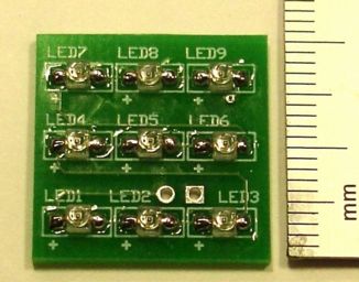
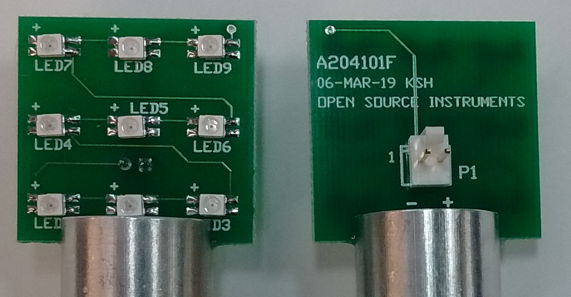
The A2041D is an adaptation of the A2041A for LEDs in PLCC4 packages. It has similar dimensions to the A2041A, with similar LED locations. The A204101D and A204101F printed circuit boards are both suitable for assembly of the A2041D.
We can equip the A2041D with any of the OVSA1 family of LEDs. The A2041D-R uses the red OVSA1S and the A2041D-A uses the amber OVSA1A. The nine red or amber LEDs have a typical voltage drop of 22 V at 50 mA. The green OVSA1G and blue OVA1B have typical forward voltage drop at 30 mA is 3.6 V, so that an array of nine would typically require 32 V, and in the worst case 38 V. If the A2041D is to be used with the LWDAQ, which provides at most 30 V, we must omit four of the nine LEDs, such as those in the corners, and short their footprints with solder lumps. We are then left with five super-bright blue or green LEDs emitting roughly 8 mW each. The A2041D-R is the array we use in the WPS2 optical wire position sensor.
The A2041N provided an array of 9 Luxeon Z LEDs. It uses circuit board A204101E.


The A2041N-B provides nine royal blue LEDs, and the A2041N-R provides nine deep red LEDs. The A2041N-B we designed for use in the alignment bars of the New Small Wheel in the ATLAS detector. The board has two wires soldered to the back side for power delivery.
The A2041W is a modified A2041A. It is 31.25 mm square and uses the A204101B printed circuit baord. It adds a visible red radial-lead LED in series with a 3.3 kΩ resistor across pins 1 and 2 of P1. We use the A2041W with the WPS Head (A2051W). The red LED turns on when we power the surface-mount infra-red LED array, drawing 5 mA away from the main array current, but showing us that the array is turned on.
S2041_1: Schematic.
A204101B: PCB for A2041A, HSDL-4400 9-LED Array.
A204101C: PCB for A2041B, HSDL-4400 9-LED Array.
A2041B.xls: BOM for A2041B, HSDL-4400 9-LED Array.
A204101D: PCB for A2041D, 4PLCC 9-LED Array..
A204101E: PCB for A2041N, Luxeon Z 9-LED Array.
A204101F: PCB for A2041D, 4PLCC 9-LED Array.
A204101F: PCB for A2041D, 4PLCC 9-LED Array.
A204101F View: View of PCB for A2041D, 4PLCC 9-LED Array.
A2041D-R.ods: BOM for A2041D-R, Red 9-LED Array.