| Schematic | PCB | Assembly |
The Bar Head (A2044) is a Long-Wire Data Acquisition (LWDAQ) Device that reads out two TC255P image sensors and four platinum 1000-Ω RTDs (resistance-temperature devices). It flashes two independent IRLED (infra-red light-emitting diode) arrays, such as the Nine-LED Array (A2041A).
We designed the A2044 for use in the alignment bars of the ATLAS end-cap muon alignment system. One A2044 at each end of an alignment bar will read out the six or eight 1000-Ω RTDs along the length of the bar, capture images from the two image sensors at either end of the bar, and flash the four LED arrays within the bar. The image sensors are close to the A2044s, while the temperature sensors and LED arrays can be up to four meters away.
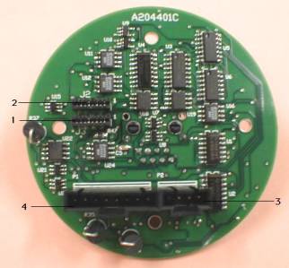
The A2044 connects to its two image sensors through two eight-way flex connectors on the board. These connectors accept 1-mm pitch flex cables, and are designed to connect to our TC255P Minimal Head (A2016). Each A2016 provides a socket for a TC255P and an eight-way flex connector. The flex cables joining the A2044 and its A2016s can be up to 45 cm long.
Here is a table of pin assignments on the eight-way flex connector. If you prefer to look at the same table in the form of a circuit diagram, you will find the diagram here.
| Pin | Function |
|---|---|
| 1 | +12 V |
| 2 | Anti-Blooming Gate (ABG) |
| 3 | Image Sensor Output (OUT) |
| 4 | Storage Area Gate (SAG) |
| 5 | Zero Volts (SUB) |
| 6 | Image Area Gate (IAG) |
| 7 | no connection |
| 8 | Serial Register Gate (SRG) |
The A2044 connects to its two LED arrays through a four-way shrouded plug. For a description of these plugs and how to prepare sockets that mate with them, see here. Each LED array requires two connections, as shown in the following table.
| Pin | Function |
|---|---|
| 1 | LED Array 1, V- |
| 2 | LED Array 1, V+ |
| 3 | LED Array 2, V- |
| 4 | LED Array 2, V+ |
The A2044 connects to four 1000-Ω RTDs through an eight-way shrouded plug. For a description of these plugs and how to prepare sockets that mate with them, see here. The connection to each RTD consists of only two wires.
| Pin | Function |
|---|---|
| 1 | RTD 1 V- |
| 2 | RTD 1 V+ |
| 3 | RTD 2 V- |
| 4 | RTD 2 V+ |
| 5 | RTD 3 V- |
| 6 | RTD 3 V+ |
| 7 | RTD 4 V- |
| 8 | RTD 4 V+ |
A 1000-Ω RTD has nominal resistance 1 kΩ at 0 C. The resistance of such a sensor increases by approximately 4 Ω/C. The combined resistance of the wires leading to a sensor adds to the resistance of the sensor itself, causing an increase in measured temperature of 0.25 C/Ω.
Example: We observed a 50 mK/m increase in measured temperature with our standard stranded-core twisted pair cables. The longest connection to an RTD in ATLAS is nearly five meters, which introduces an increase in absolute temperature measurement of 0.25 C. But the ATLAS temperature sensors will be calibrated a 20 C, thus removing any absolute error in the error in the absolute temperature measurement, either due to cable resistance or the sensor itself. Our ATLAS temperature sensors are accurate to ±0.3 C at 0 C, so the error due to connecting wire resistance is comparable to the error due to the sensor itself. Furthermore, if we know the length of the cable, we can calculate and remove the effect of its resistance.
The following versions of the A2044 exist at the time of writing.
| Version | Description |
|---|---|
| A2044Y | One orange dot on PCB, PCB either A204401B or A204401C. |
| A2044A | Two orange dots on PCB or no dots on PCB, PCB either A204401B or A204401C. |
| A2044B | As A2044A, but R26 and R29 are 1K0 and C13 has been removed. |
| A2044C | As A2044B, but PCB is A204401D. |
| A2044D | As A2044C but with 5.1-V zener diode from VL to 0V. |
| A2044E | As A2044D but J1 is right-angle. |
The dynamic range of the temperature measurements made by each of these versions varies.
The A2044 complies with the Long-Wire DAQ specification. It is LWDAQ Device Type 2 (TC255P). Element numbers 1-2 select the two image sensors on sensor jobs, and element numbers 1-2 select the two LED arrays on a flash job. The RTDs do not have element numbers because we select the RTDs directly by setting the A2044 command bits (see next paragraph).
| DC16 | DC15 | DC14 | DC13 | DC12 | DC11 | DC10 | DC9 | DC8 | DC7 | DC6 | DC5 | DC4 | DC3 | DC2 | DC1 |
|---|---|---|---|---|---|---|---|---|---|---|---|---|---|---|---|
| TB | T4 | T3 | T2 | T1 | ON2 | ON1 | CCD1 | WAKE | LB | TT | TSEL | IAGD | SAGD | SRGD | DCEN |
To determine the command word that will implement a particular operation on the A2044, write out sixteen bits in a row, starting with bit sixteen (DC16) on the left, and ending with bit one (DC1) on the right. Set each bit to zero or one as you require. The left-most four bits form the most significant nibble of the sixteen-bit command word. The right-most four bits are the least significant nibble. Translate each nibble into a hex digit, and you have the hex version of the command word.
Example: To select the top temperature reference, we must set the following bits: TSEL (DC5), TT (DC6), and WAKE (DC8). All other bits should be cleared. So we compose the following binary number: 0000 0000 1011 0000, which translates to 0x00B0 (here we use 0x to mean hexadecimal).
You will find the schematic of the RTD readout circuit here. The circuit is based upon that of the Resistive Sensor Head (A2053A).
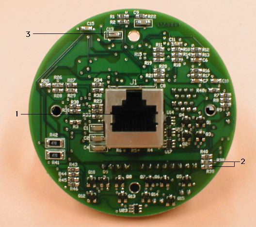
The measurement current the A2044 applies to its RTDs depends upon resistor R39 on the bottom side of the board (see photographs above and the schematic). The measurement current is equal to 600 mV divided by the resistance of R38. The dynamic range of the A2044 temperature measurement will be centered upon 20 C if the value of R38 is exactly equal to that of R39. If the two resistors are within 1% of one another, the center of the dynamic range will be between 17 C and 23 C. On the A2044A and A2044B, R38 and R39 are 0.5% resistors of value 2 kΩ. The RTD measurement current is 300 μA. The dynamic range of the temperature measurement is inversely proportional to the RTD measurement current and the gain of each analog amplification stage in the temperature measurement path. The A2044A we shipped with two different gains, but the A2044B has only one gain, and its dynamic range is at least ±30 C.
You select the first image sensor (connected to J3) by unasserting LB and TSEL, and asserting CCD1. Select the second sensor (connected to J2) by unasserting LB, TSEL, and CCD1.
With DCEN and SRGD asserted (DC1 and DC2 HI), T+/T- clocks image sensor pixels directly. Logic HI selects reset level, logic LO selects pixel intensity. Logic LO must endure for at least 100 ns, logic HI for at least 300 ns. The maximum recommended clock speed is 2 MHz.
With TSEL and LB unasserted, the differential voltage returned on R+/R- is a linear function of the output from one of the image sensors. Either the voltage represents the reset (or background intensity) of the image sensor, or it represents the intensity of a pixel. The difference between the voltage returned for a pixel intensity and the voltage returned for the background intensity is proportional to the number of electrons accumulated in the pixel. At pixel saturation, this difference is typically 1V for the A2044A and 1.3V for the A2044Y.
You will see all the steps required to control and read out an A2044 in Rasnik.tcl and Thermometer.tcl. These are the TclTk scripts that define the Rasnik and Thermometer instruments in our LWDAQ Software. To see how we compose TCPIP messages for communication with a LWDAQ Driver, see Driver.tcl. The A2044 Tester script is a LWDAQ Tool that tests the cameras, light sources, and thermometers of the A2044. You can run it in LWDAQ with "Run Tool" in the Tools menu. In the paragraphs below, we describe these steps, but if you want to implement your own data acquisition software, you will need to look at the TclTk scripts to understand the details of the process.
The A2044 provides exposure of the TC255P without anti-blooming. Anti-blooming exposures are good for pictures showing where things are, but they compromise the linearity of the pixel response. Implementing the anti-blooming adds components to an already crowded device. To read out image sensor 1 (connected to J3), specify device element number 1 before you begin the exposure. To read out image sensor 2 (connected to J2), specify device element number 2 or 0. You obtain a new image with the following sequence of LWDAQ Driver jobs: move, wake, flash, alt_move, and read. The image will now be in the driver memory. Before any device-dependent job, you must sepcify the A2044 device type, which is 2. For a detailed description of the image read-out sequence, see the Operation section of the A2051 Manual. The A2051 readout is identical to that of the A2047, except that the A2047 does not support anti-blooming.
To flash one of the two LED arrays, execute a flash job. To flash LED array 1, specify device element number 1. Alternatively, you may wish to turn one of the arrays on by writing your own command word to the device. To turn on LED array 1, set bits DC8 (WAKE) and DC10 (ON1).
To read out the temperature sensors, you transmit command words one at a time to the A2044 using your LWDAQ Driver's command_job. The A2044 has a current source which you can, by sending the correct command word, direct through one of six resistors. Two of the resistors reside on the A2044 board itself, and are 0.01% precision wire-wound resistors of 1060 Ω and 1100 . The 1060 Ω resistor provides a low-temperature reference point of 15.4 C for standard 1000-Ω RTDs, and the 1100 Ω resistor provides a high-temperature reference point of 25.7 C.
When you select the high-temperature reference, by setting bit DC6 (TT) in the command word, the A2044 sends back an analog voltage that is a linear function of the high-temperature reference resistance. You digitize this voltage using the LWDAQ Driver. The A2037 driver, for example, provides a sixteen-bit ADC which will do the job with sufficient accuracy to obtain 20 mK resolution. When you set bit DC16 (BT), you obtain a voltage from the A2044 that is the same linear function of the low-temperature resistance. Now you can select the four RTDs in turn, and interpolate between the top and bottom reference voltages to obtain the temperature of the RTD.
| Resistor Name | Command | Comment |
|---|---|---|
| TT | 0x00B0 | Top Temperature Reference |
| TB | 0x8090 | Bottom Temperature Reference |
| T1 | 0x0890 | First Sensor |
| T2 | 0x1090 | Second Sensor |
| T3 | 0x2090 | Third Sensor |
| T4 | 0x4090 | Fourth Sensor |
Example: We have a Bar Head (A2044) connected to an LWDAQ Driver (A2037). We connect a single platinum temperature sensor to the first two pins of P1 on the A2044. We use the A2037 command job to send command 0x00B0 (hexadecimal) to the A2044. This command wakes up the board, selects the temperature sensor data, and selects the top reference temperature. We allow 1 ms for the A2037's 10 kHz input filter to settle. We execute an adc16 job and retrieve the sixteen-bit result. For an A2044B this will be between 29,000 and 31,000. We send command 0x8090 to the A2044 and select the bottom reference temperature. We wait ms, and execute another adc16 job. The result should be between 38,000 and 41,000. We select our temperature sensor, which is T1, with command 0x0890, wait 1 ms, and execute an adc16 job. The result should be between 0 and 65,500 provided the sensor temperature is between -10 C and +50 C. We know that the top temperature reference is 25.7 C, and the bottom is 15.4 C, so we interpolate between the two to obtain the temperature of our sensor. We are assuming, of course, that the sensor is a 1000-Ω RTD. Note that the high-temperature reference voltage at the A2037's ADC is lower than the low-temperature reference voltage.
Example: We add to the above set-up three more temperature sensors on the six remaining pins of P1. Each sensor we wire to adjacent pins. We select the sensor on pins 3 and 4 with command 0x1090, the sensor on pins 5 and 6 with 0x2090, and the sensor on pins 7 and 8 with 0x4090. After we select each sensor, we wait 10 ms, digitize the returned voltage, and interpolate using our previously-obtained reference points to obtain the sensor temperature.
We use a reference socket to test our A2044 boards. The reference socket is an 8-way socket we connect to P1. Pins 1 and 2 of the referenec socket connect to a 1060-Ω 0.01% resistor, pins 3 and 4 connect to a 1100-Ω resistor, pins 5 and 6 are connected directly together with a wire, and pins 7 and 8 are left open-circuit. The temperature we measure on T1, using the procedure given in the above examples, should be within 0.03 C of the bottom temperature reference (15.38 C). The temperature we measure on T2 should be equally close to the top temperature reference (25.69 C). From T3 we get the low-temperature end of the A2044's dynamic range. For an A2044B this should be below 10 C, allowing you to use an ice-water bath to calibrate your temperature sensors. From T4 we get the high-temperature end of the dynamic range. For an A2044B this should be above 50 C, allowing you to measure ambient temperature in most electronic equipment.
The A2044 is asleep when it powers up. It also goes to sleep when you execute a LWDAQ sleep job. To measure the propagation delay of signals travelling from the driver to the A2044 and back again, you execute a LWDAQ loop job and read the loop time out of the driver.
We picked an A2044A at random and measured its power consumption both asleep and awake, as shown in the following table. We know from experience that the power consumption when capturing live images is a few milliamps higher on all supplies, but we did not perform this measurement for the A2044.
| State | +15 V | -15 V | +5 V |
|---|---|---|---|
| Asleep | 400 μA | 100 μA | 6 mA |
| Awake | 65 mA | 50 mA | 6 mA |
The +5V sleeping power consumption of the A2044 exceeds the LWDAQ Specification by 1 mA. We discovered this only in 2008, after the circuit had been in use for five years. Until then, we had been under the impression that the +5V sleeping consumption was only 2 mA. We are not sure why the A2044 draws 6 mA when asleep, but we'll look into it when we have time.
We subjected an A2044A to 30 krad of ionizing radiation at 20 krad/hr with power applied to the circuit. It was fully-functional a week after the exposure. We observe less than a 1 mA increase in current consumption from 3.3 V. We exposed another A2044A to 100 krad of ionizing radiation at 20 krad/hr with power applied to the circuit. Current consumption from +3.3V increased from 3 mA to 70 mA a week after the irradiation and 30 mA two weeks after exposure. Five years after irradiation the quiescent current is 25 mA. But the 74VHC123 is not pulsing. Transistor Q4, a discrete MOSFET in the A2044A, is not switching properly because of a combination of a drop in the 3.3-V power supply and a change in its threshold voltage. The analog switch DG419 remains functional. This chip, although a vulnerable analog switch in the same family as the DG411 of the A2036 and A2046, was not under power during the irradiation. The DG419 receives power only during active data acquisition from the A2044. We conclude that the A2044 can tolerate at least 30 krad, but is likely fail before we reach 100 krad, even at low dose rates. See here for a discussion of the radiation tolerance of the A2047, which is a camera circuit very similar to the A2044.
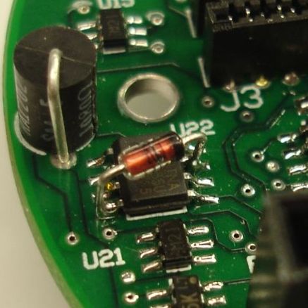
The A2044C has proved unreliable because of repeated failures of its INA155 instrumentation amplifier. Approximately one out of four circuits sent to CERN failed in the field within a month. Every broken circuit returned to us has the same problem. The instrumentation amplifier, U22, is broken. In each case, when we replaced U22, the circuit worked again. The failures took place even though the RTDs were glued in place and connected to the A2044 at all times. We decided that the most likely cause of problems with U22 was U24 driving VL higher than +5V on power-up. We thought we had eliminated spikes in VL as a cause of failure when we disconnected and re-connected the A2044 power supplies at random for a few days continuously in our laboratory. We saw no failure of U22 during our tests. The A2044D has a 5.1-V zener diode across the U22 power supply to absorb the energy of spikes on VL and protect U22.
Another problem we had with the A2044C was failure due to mounting without nylon insulating washers. When there is no washer between the screw and the circuit board, the screw near U1 cut through the solder mask over the trace running from U24-5 to R30. Pin U24-5 gets shorted to J1's shield and the A2044's temperature readings begin to drift and go wrong over time. The shield is not connected directly to the local circuit 0-V, but instead through C5, a 10-nF capacitor. Pin U24-5 is the VCOM voltage, which U24 buffers and distributes on U24-7. It seems that connecting the shield to U24-5 affects VCOM so as to disturb the temperature measurements. This does not surprise us. We conclude that nylon washers are essential when mounting the A2044, and we made sure that CERN and Freiburg began using such washers in December 2005.
In July 2006, we realized that the connection between U24-5 and the J1 shield could cause VCOM to spike above VL, which would damage U22. If that's the case, then we see why the A2044C survived our power switching tests: U24-5 was not connected to J1's shield in our tests. The reason we have had no failures in the A2044D is because CERN and Freiburg are mounting the A2044Ds with insulating washers that prevent the connection of U24-5 to J1's shield, not because the zener diode is protecting U22. Because this remains a hypothesis, we will continue shipping A2044Ds to CERN.
Note: All our schematics and Gerber files are distributed under the GNU General Public License.