 Programmable Logic Head (A2060) Manual
© 2004, Mike Bradshaw, Brandeis University© 2008-2018, Kevan Hashemi, Brandeis University
The Programmable Logic Head (A2060) is a LWDAQ device built around an in-system programmable logic device (PLD). It provides ten general-purpose logic IO (input-output) lines and a through-hold breadboard area for specialized circuits. The following adaptations of the board exist. Click on the links to get to their dedicated manual pages.
| Version | Description |
|---|---|
| A2060A | Basic circuit, A206001B PCB. |
| A2060B | Basic circuit, A206001D PCB. |
| A2060C | RS-232 Interface |
| A2060H | H-Bridge Motor Driver |
| A2060L | Lamp Controller |
| A2060M | Stage Controller |
| A2060P | Pulse Counter |
| A2060R | Door Interlock Logic. |
| A2060X | X-Ray Controller |
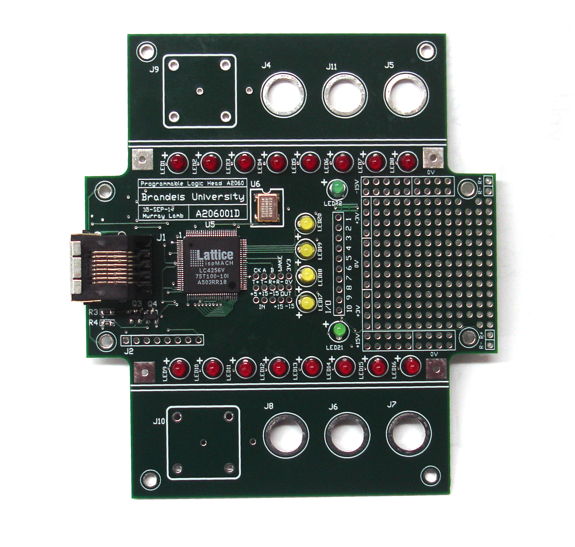
The breadboard area has access to +15V, +3.3V, 0V, and −15V power supplies, as well as ten programmable digital input-output signals. The ±15 V is switched on and off by the WAKE bit in any LWDAQ commane we send to the device. When the device powers up, the ±15V will be off. The state of the ±15 V power supplies is indicated by two green LEDs. The device provides four user-programmable yellow LEDs (TP1 to TP4) and sixteen user-programmable red LEDs (LED1 to LED16).

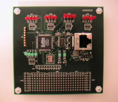
The A2060A, shown below, was the A2060 version we used from 2004-2014. Both are electrically equivalent. The A2060B provides more expansion space and footprints for connectors, and fits into a PPL enslosure once the wings are cut off.

The A2060 complies with the LWDAQ specification with the exception of its +5-V current consumption. Its logic chip and oscillator together consume around 40 mA when the board is awake or asleep. The LWDAQ maximum is 5 mA when asleep and 20 mA when awake. Thus the A2060 is not suitable for incorporation into large LWDAQ systems with long cables and multiplexers.
The first working circuit board, now obsolete, was the A206001B. This board had two major problems. First, its logic chip was rotated by 90° without marking on the silk screen, which led to numerous errors in assembly. Second, the holes in the breadboard area were too small to accept standard through-hole component legs. The second working circuit boad is the A206001D. This board has one minor problem: all the LEDs are marked "+" on the wrong side, so if you load them with the anode by the "+" mark, they will be in the wrong way around.
The A2060B firmware checks all LEDs on the board, implements a LWDAQ command and address receiver, and a byte transmitter to respond to byte reads from the LWDAQ Driver. The first version JEDEC file is A2060B01.jed and ABEL source code is A2060B01.able. You may find newer versions in our code directory. In the first version, you connect power and the sixteen lights LED1..LED16 start illuminating one after the other. You change direction by setting DC2 with a command word (send command 0x0002, for exampple). The byte that the board transmits to the LWDAQ driver increments after each transmit, so you can get a gray scale image with the Terminal Instrument if you set the image width to 256. Reset the counter with DC1 (send command 0x0001, for example). The four lamps TP1..TP4 are DC1..DC4.
The A2060A was designed in 2004. Its schematic was four pages long. It used LED arrays and resistor arrays. In 2012 we switched to single 3-mm axial LEDs and single P0805 resistors. We re-drew the schematic in two pages. You will find the new pages below. Extensions to the A2060A circuit each present pages 3 and up, because the core circuit covers pages 1 and 2.
S2060_1: LVDS Transceiver and Logic Chip.
S2060_2: Light Emitting Diodes and IO Lines.
A2060A.bom: Bill of Materials for A2060A.
A2060B.bom: Bill of Materials for A2060B.
S2060C_3: Expansion Circuit for A2060C, the RS-232 Interface.
S2060L_3: Expansion Circuit for A2060L, the Lamp Controller.
S2060H_3: Expansion Circuit for A2060H, the H-Bridge Motor Driver.
S2060X_3: Expansion Circuit for A2060X, the X-Ray Controller.
S2060L_3: Expansion Circuit for A2060L, the Lamp Controller.
S2060P_3: Expansion Circuit for A2060P, the Pulse Counter.
A206001B: A206001B Printed circuit board files.
A206001D: A206001D Printed circuit board files.
A206001D_GTO: A206001D Top Overlay.
A206001D_GBO: A206001D Bottom Overlay.
Firmware: Various versions of the firmware. All versions include a command receiver.
ispMACH4000: Data sheet for the programmable logic chips. The V-series parts with the -100T are compatible with the A2060A/B circuit boards. We like to use the LC4256V-100T.
Programming Instructions: How to program the logic chip on another of our circuits, the A2037. These instructions apply almost exactly to the A2060. You may also consult the Lattice Semiconductor website to purchase programming cables and download programming software, which is free.