The RS232 Interface (A2060C) provides a three-wire 9600-baud RS232 interface. The A2060C is a Long-Wire Data Acquisition (LWDAQ) Device. It is a variant of the LWDAQ Programmable Head (A2060A). The A2060C uses a MAX222 interface chip to generate RS232 voltage levels on its transmit line, and to receive RS232 voltage levels on its receive line.
The A2060C operates with the Terminal Instrument. The A2060C provides a 9-pin DIN plug with the following RS232 pin assignments.
| Pin | Description |
| 2 | Receive Serial Input |
| 3 | Transmit Serial Output |
| 5 | Zero Volts (0V) |
The A2060C uses the LC4256V-10T100I programmable logic chip from Lattice Semiconductor. This chip provides 256 generic logic blocks, which is more than enough to implement the RS232 Interface logic. You will find the latest version of the P2060C code here.
The A2060C complies with the LWDAQ specification with the exception of its +5-V current consumption. The A2060C consumes 60 mA when asleep and 65 mA when awak. The LWDAQ maxima are 5 mA and 20 mA respectively. Thus the A2060C is not suitable for incorporation into large LWDAQ systems with long cables and multiplexers. The A2060C is LWDAQ Device Type 3 (data device). It implements no element numbers. Its command bit allocation is as follows.
| DC16 | DC15 | DC14 | DC13 | DC12 | DC11 | DC10 | DC9 | DC8 | DC7 | DC6 | DC5 | DC4 | DC3 | DC2 | DC1 |
|---|---|---|---|---|---|---|---|---|---|---|---|---|---|---|---|
| SD7 | SD6 | SD5 | SD4 | SD3 | SD2 | SD1 | SD0 | WAKE | LB | DRX | DTX | X | X | X | X |
When the A2060C receives a new command word with DRX set to 1, it transmits bits SD0 through SD7, with SD0 first, on pin 3 of its 9-pin DIN connector. When DTX and LB are 1, the A2060C is ready for byte transfer to the LWDAQ driver. It waits for a stop bit from the driver. When it receives the stop bit, the A2060C transmits the next byte it receives over its RS232 interface to the driver. If DTX is 0 and LB is 1, then the A2060C loops back the logic signal it receives from the LWDAQ Driver, as required by the LWDAQ specification.
Starting with firmware version two, when the A2060C first receives DTX, the A2060C transmits an XON (decimal ASCII character 17) through its RS-232 port, to let the device at the other end of the cable know that the A2060C is ready to receive bytes. We assume that the device at the other end can respond to both XON and XOFF (decimal ASCII character 19). The A2060C does not send an XOFF atomatically at any time. Instead, it will do so when we send an XOFF command with DRX. By this means, the A2060C can transmit characters to an RS-232 device and be sure to receive its response, despite the delay of a millisecond or two that the LWDAQ system imposes between the final transmit character and the time when the A2060C can be ready to receive characters.
To determine the command word that will implement a particular operation on the A2060C, write out sixteen bits in a row, starting with bit sixteen (DC16) on the left, and ending with bit one (DC1) on the right. Set each bit to zero or one as you require. The left-most four bits form the most significant nibble of the sixteen-bit command word. The right-most four bits are the least significant nibble. Translate each nibble into a hex digit, and you have the hex version of the command word.
Example: To cause the A2060C to transmit byte 0xF0 through its RS232 transmit pin, send command word 0xF0C0. This will set the serial transmission data to 0xF0 and provoke transmission.
Example: To cause the A2060C to transmit the next RS232 byte back to the driver when you execute a read_job with device_type 3 (DATA), send command word 0x00D0. To take the A2060C out of its waiting state, send command word 0x0080 and it will return to its rest state within a fraction of a microsecond.
The LWDAQ read_job applied to a LWDAQ device of type data_device (3) will send a 125-ns low pulse to the target device, and then wait for the device to transmit an eight-bit number. The beginning of the eight-bit transmission is a 50-ns low pulse, followed by the eight bits of the freshly-received RS232 byte, with the most significant byte first. Note that RS232 transmission occurs with the least significant byte first. The entire transmission from the A2060C to the LWDAQ Driver takes only 500 ns.
| State | +15 V | -15 V | +5 V | Total Power |
|---|---|---|---|---|
| SLEEP | 0 μA | 0 μA | 60 mA | mW |
| WAKE | 2 mA | 2 mA | 65 mA | mW |
The LWDAQ limit for sleeping power consumption from the 5V supply is 5 mA, and for awake consumption it is 20 mA. The A2060C exceeds these limits.
The A2060C transmits data byte-by-byte across an RS232 serial connection at 9600 baud (one byte per millisecond) with one start bit and one stop bit. It receives data in the same way, and stores the received bytes in a register that the LWDAQ Driver can upload into its RAM with a read job.
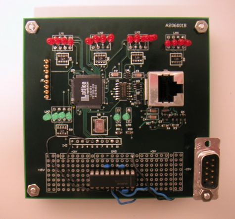
The A2060C provides a generous number of LED indicators. From left to right along the top of the board in Figure 1, the red LEDs are named LED1 through LED16. The first eight, from left to right, are DC1 to DC8 in the most recently received command word. Thus the eighth LED from the left turns on when WAKE is set, and the fifth from the left turns on when DTX is set. The eight LEDs on the right give the byte value most recently received through the RS232 interface. The most significant bit is LED9, and the least significant is LED16, so that the byte reads from left to right.
The four green LEDs together on the middle-left are for hardware diagnostics. You can figure out what they mean by looking at the P2060C firmware. They are connected to logic signals TP1 through TP4. The two remaining LEDs indicate that the on-board ±15V power supplies are turned on. These are not used by the A2060C, but are available on the patch panel at the bottom of the board.
Plug the A2060C into the LWDAQ. Connect your serial cable to the 9-pin DIN plug. Make sure that the cable delivers its RS232 incoming signal to pin 2 of the connector, and carries away the signal from pin 3. Make sure the RS232 transceiver at the other end of the cable does not expect hardware data flow control signals, uses eight data bits, one start bit, and one stop bit, and runs at 9600 baud.
Open the Terminal Instrument in the LWDAQ Software. Read the help that goes with it in the LWDAQ Manual. If you are using LWDAQ 6.8.15 or earlier, download the latest version of the software.
The A2060C transmits and receives RS232 data in only one format: one start bit, eight data bits, no parity bits, and one stop bit at 9600 baud. The 9-Pin Din plug transmits on pin 3 and receives on pin 2. It uses pin 5 as its zero-volt reference. Please do not confuse zero volts with ground. If you connect the shield of the RS232 cable to pin 5, you will be connecting the LWDAQ device's zero-volt power to external chassis ground, thus inviting ground loop noise into your data acquisition system.
The A2060C does not support simultaneous transmission and reception of data. The A2060C has a one-byte receive buffer and a one-byte transmit buffer. It cannot accumulate data either from the RS232 interface or from the LWDAQ driver. The A2060C either receive characters over RS232 and transmit them immediately to the LWDAQ Driver, or it can do the opposite. The LWDAQ and the remote system at the other end of the RS232 cable must take turns transmitting to one another. If their transmissions are of variable length, they must mark the end of their turn with termination characters. The A2060C transmits an XON character when it is ready to receive data, and this makes it possible for the device at the other end of the RS-232 cable to refrain from sending data until the A2060C is ready. The A2060C, however, cannot respond to XOFF or XON characters itself, although it will receive them and pass them on to the LWDAQ driver.
See the Terminal Instrument manual entry for an explanation of how the Terminal Instrument operates the A2060C.
When it transmits data through the A2060C to the RS232 link, the driver sends consecutive command words with the DRX set to 1 and the upper eight bits set to a data byte. Upon receiving the command, the A2060C transmits the data byte through its RS232 interface, which takes about a millisecond at 9600 baud. The driver should refrain from sending another command word until a millisecond has passed. Any command sent before the A2060C has finished sending its data byte will be ignored. You can use the driver's delay timer to generate this 1-ms delay, but we find that with the A2037E the time it takes to set up a new command transmission is in fact 2 ms, so we do not need to insert a delay in the data transmission process.
When the driver transmits 10,000 bytes of data, the LWDAQ driver sends 10,000 LWDAQ commands to the A2060C. Each command takes 4 μs to transmit, and must be followed by a minimum 1-ms delay for 9600-baud transmission of the byte across the RS232 interface. With the A2037E we find that the sustained data rate is roughly 400 bytes/second, limited by the time it takes the A2037E to receive and process instructions through its TCPIP interface.
When it receives data through the A2060C from the RS232 link, the driver sends a command word with DTX set to 1. The A2060C waits for a stop bit. When it receives the stop bit, it waits for a byte to arrive through its RS232 interface. When the byte arrives, the A2060C transmits it immediately to the driver by byte transfer. After the byte transfer, the A2060C waits for another stop bit, and sends the next RS232 byte. In the driver, each stop-bit and byte-transfer is one execution of a read job. The Terminal uses the driver's repeat counter to cause the driver to execute the read job rx_size times in a row.
Note: All our schematics and Gerber files are distributed under the GNU General Public License.
S2060_1 LVDS Transceiver/Power Supplies