Lamp Controller (A2060L) Manual
©2012 Kevan Hashemi,
Open Source Instruments, Inc.
Contents
Description
Operation
Controller
Related Circuits
Electronics
Description
The A2060L is a LWDAQ device that produces sequences of pulses autonomously so as to flash or stimulate lamps or other external devices. We configure the A2060L's pulse sequence with one or more LWDAQ commands, and then instruct it to execute the sequence with a final command. The circuit provides two switching outputs: a TTL logic signal and a 0-11 V analog signal.
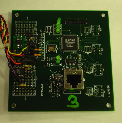
Figure: The Lamp Controller Head (A2060L). The twisted pairs carry the three indicator lamp currents and the two output signals. There are six green LEDs on the circuit board. They are from left to right: stimulus running, interval clock, randomizer enabled, lamps are on, −15V power on, and +15 V power on.
The A2060L is a Programmable Logic Head (A2060) with circuits that produce the analog and logic output signals, as well as drive the indicator lamps. Two BNC sockets deliver the lamp control signals to some external lamp driver circuit. Two blue LEDs next to these sockets indicate the state of the output.
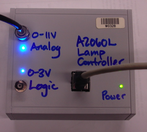
Figure: The Lamp Controller (A2060L). The enclosure is an A31GY from Serpac.
The panel LED next to the logic output is on when the logic output turns on the external lamp. Because the polarity of logic signal can be configured as positive-true or negative-true, the LED may be on when the logic output is 0 V. But by default, the logic output is positive-true, so the LED will be on when the output is HI. A TTL HI is anything above 2.4 V, but our circuit outputs 3.3 V.
The analog output is always 0 V when the external lamp should be off, and 0-11 V when the lamp should be on. We assume the lamp driver will take this lamp control voltage and use it to determine the brightness of the lamp. The blue indicator LED next to the analog output has brightness proportional to the analog voltage. When the analog output is 11 V continuously, the blue LED is so bright it is hard to look at directly when at arm's length.
We designed the A2060L to control LED drivers that flash LEDs in brain tissue in optogenetics experiments. But it could be used to provide sequences of pulses for any other purpose. In the Operation section below, we describe the details of how to control the A2060L with the LWDAQ. In the Controller section, we present a script that makes it easy for you to generate the code that produces the A2060L stimuli you want, and so transfer these stimuli to other scripts.
Operation
To operate the A2060L, we configure it with one or more commands and then instruct it to start the sequence we have defined. The pulse length is the length of the on-pulses in milliseconds. The interval length is the average time between pulses. The sequence length is the number of pulses the sequence contains. The sequence ends when this number of pulses have occured. The time at which a pulse occurs within its interval can be fixed or random according to enable randomize. The polarity of the logic output can be positive or negative-true according to set polarity.
The A2060L is a LWDAQ device. It obtains power for its internal logic from the LWDAQ. The LWDAQ command bits are assigned as follows.
| DC16 | DC15 | DC14 | DC13 | DC12 | DC11 |
DC10 | DC9 | DC8 | DC7 | DC6 | DC5 |
DC4 | DC3 | DC2 | DC1 |
|---|
| D7 | D6 | D5 | D4 | D3 | D2 |
D1 | D0 | WAKE | LB | X | X |
OC3 | OC2 | OC1 | OC0 |
Table: Command Bit Allocation of the A2060L. An "X" means the command bit serves no function.
Bits D7..D0 form the data byte that is written to an internal registers on the A2060L. The OC3..OC0 bits form the operation code that selects which register is written. The following table give the operation code functions, and summarizes how the data value affects each operation.
Code
(Decimal) |
Code
(Hex) |
Operation |
Data
Function |
| 0 | 0 | clear settings | none |
| 1 | 1 | start stimulus | 1 to start, 0 to stop |
| 2 | 2 | set polarity | 0 for positive, 1 for negative |
| 3 | 3 | set brightness | ×11.5 V ÷ 256 |
| 4 | 4 | set pulse length high byte | ×256 ms |
| 5 | 5 | set pulse length low byte | ×1 ms |
| 6 | 6 | set interval length high byte | × 256 ms |
| 7 | 7 | set interval length low byte | × 1 ms |
| 8 | 8 | set stimulus length high byte | × 256 pulses |
| 9 | 9 | set stimulus length low byte | × 1 pulse |
| 10 | A | enable randomizer | 1 to enable, 0 to disable |
Table: Operation Code Functions. We give the codes in decimal and hex. The operation code is OC3..OC0 in the command bits, while the data is D7..D0.
We can send commands to the A2060L using the Diagnostic Instrument. We enter the hexadecimal value of the sixteen-bit command in the Command window, direct the instrument at our A2060L target, and press Transmit. We can even enter several commands into the Command window. But we prefer use the following script to test the operation of the A2060L. Copy and paste it in the LWDAQ Toolmaker and adjust the ip_addr and driver_socket to select your A2060L in your own LWDAQ sytem. When you press Execute a window will open with an entry box to list your commands and a Transmit button.
# Send a sequence of LWDAQ commands to a device
# upon button press. List the commands in the
# entry box in hexadecimal format.
set p(commands) "0080 FF83 2087 0185 0181"
set p(text) $t
set p(ip_addr) "129.64.37.88"
set p(driver_socket) 5
set p(mux_socket) 1
button $f.transmit -text Transmit -command Transmit
entry $f.commands -textvariable p(commands) -width 60
pack $f.transmit $f.commands -side left -expand yes
proc Transmit {} {
  global p
  set sock [LWDAQ_socket_open $p(ip_addr)]
  LWDAQ_set_driver_mux $sock $p(driver_socket) $p(mux_socket)
  foreach c $p(commands) {
    LWDAQ_transmit_command_hex $sock $c
  }
  LWDAQ_socket_close $sock
  LWDAQ_print $p(text) $p(commands)
}
In our example, we begin with code 0080, which executes operation zero, or clear settings. All the length values are now zero, the polarity of the output is positive-true and the randomizer is off. The 8 in the command is there to wake up the A2060L's internal ±15 V power supplies, which are used by the analog output circuit. All the codes we send to the A2060L have an 8 in the same hexadecimal digit.
The FF83 code sets the analog on-voltage to its maximum value, using the number 255 for the data. When the lamp is on, the analog voltage will be roughly 11.5 V. When it is off, the voltage will be 0 V.
The 2087 sets the low byte of the interval length to 20 hex, which is 32, so that the average pulse separation will be 32 ms. We do not have to set the high byte to zero because we already did that with the clear operation.
The 0185 sets the low byte of the pulse length to 1, so we will have 1-ms pulses. Once again, the high byte of the pulse length is already zero. The final command sets the stimulus in motion by sending a one with the start stimulus operation.
You will note that our commands do not specify the number of pulses. The stimulus length is zero. The zero value indicates that the A2060L should continue flashing for an infinite number of pulses.
The commands "0080 8083 3285 0786 D087 2788 1089 018A 0181" configures the A2060L to send 1000 pulses each of duration 50 ms with average spacing 2000 ms, but random displacement of pulses is turned on. The analog voltage would be 5.75 V.
The commands "0080 DE83 0585 3287 6489" specify 100 pulses of 5 ms with fixed interval 50 ms and output voltage 10 V. But we have not yet sent the start command, 0181, so in this case the A2060L is ready to perform this stimuls when it receives a start command. Once the stimulus is completed, we can send another start command and it will begin again. If we send the start command before the stimulus is completed, the start command is ignored. If we want to stop a stimulus, we use a stop comamnd, 0081. To re-start we use a stop followed by a start, "0081 0181".
If we want to turn the lamp on continuously, we send a pulse length that is greater than the interval length, and leave the stimulus length at zero. Thus "0080 FF83 0285 0187 0181" asks for 2-ms pulse with 1-ms period and so results in the lamp being turned on all the time.
The A2060L uses a fifteen-bit linear shift register to generate a pseudo-random sequence of 32,767 fifteen-bit numbers. It uses these numbers, to offset the output pulse from the start of the pulse interval. The interval is a count-up to 40,000, so the random number displaces the pulse up to 82% of the way through the interval. If the pulse is longer than 18% of the interval, it can be cut short by the end of the interval. With the enable randomize instruction we can turn on or off the displacement of pulses in time by the randomizer.
The operation codes and pulse sequencing are defined in the A2060L's programmable logic chip. You will find the source code of the logic program in the Code Directory, with a name like P2060Lxx.ABL.
Controller
The Lamp Controller script is a LWDAQ Tool you can run in the LWDAQ program. It creates the following control panel for defining and transmitting stimulus instructions to the A2060L.
Figure: The Lamp Controller Tool on MacOS.
The tool converts decimal values into the sixteen-bit binary commands understood by the A2060L. It will print out in its text window a script that creates the effect of its Stimulate button. You can cut and paste this script into other programs so as to implement these effects without having to work out all the binary commands for yourself.
We use the A2060L to provide LWDAQ-controlled current for LEDs with the help of the A2060LC Current Source circuit. We present the A2060LCS circuit diagram below. We plug the A2060L analog output into P1 and our LED into P2. Power comes from an LWDAQ cable plugged into J1.
Figure: Current Source A2060LCS For Use With A2060L Analog Output.
We measure the power emitted by LEDs using the SD445 photodiode. This device is 10 mm × 10 mm and provides linear response to any given wavelength, with slope given by the sensitivity graph shown below.

Figure: SD445 Photodiode Response Versus Wavelength.
We can use this photodiode with no biase if we like, by connecting it directly to a current meter. But when we want to measure the power of light pulses, we prefer to reverse-bias the diode and run its current through a resistor so we can monitor the changes with an oscilloscope. When we apply reverse bias we also reduce the diode's junction capacitance.
We measure pulse power with the LWDAQ Voltmeter Instrument and an Input-Ouput Head (A2057A). We use the breadboard area on the A2057A to provide a two-pin plug for the photodiode, with +15-V biase current and a detection resistor. We connect the voltage on the resistor to the X1 input of the A2057A, and so we can record and display this voltage versus time with the Voltmeter Instrument, while at the same time controlling the current through the light source using the A2060L and the A2060LCS.
With a blue 470-nm LED such as the EZ500, we can supply pulses of 100-mA to the LED and hold the SD445 directly over the light-emitting surface. With 100 mA of current in this LED we expect of order 70 mW of 470-nm blue light emitted. We can collect all of this with our SD445 provided we place the detector close enough. The sensitivity of the SD445 to 470-nm blue light is 0.2 A/W so for 70 mW we should get 14 mA. When this current passes through a 100-Ω resistor it develops 1.4 V. With 15-V reverse bias, the SD445 junction capacitance is around 400 pF so the time constant of our resistor and the diode capacitance is only 40 ns, which is much less than we need for 1-ms pulses. We set up the Voltmeter Instrument to look at channel X1 on our A2057A and we see pulses of voltage. The Voltmeter gives us the root mean square amplitude of the resistor voltage, and also estimates the fundamental frequency of the pulse train. With a square wave pulse train, we can easily convert the amplitude to the height of the square wave.
The Lamp Controller tool provides an interface for defining pulses for LWDAQ devices. The A2060L is one device the tool will control. The Command Transmitter (A3023CT) is another. The Command Transmitter produces pulses of 146-MHz radio-frequency power instead of control voltages. These pulses are intended to turn on the lamp in an Implantable Lamp (A3024A), so we see that the software interface for the A3024A pulse control is the same as that of an LED we attach to the A2060L and the A2060LCS.
Electronics
For more design details, see the A2060 Manual.
S2060_1: LVDS Transceiver and Logic Chip.
S2060_2: Light Emitting Diodes and IO Lines.
S2060L_3: Expansion Circuit for A2060L, the Lamp Controller.
S2060LC_4: Auxilliary Circuit for A2060L, a voltage to current amplifier.