 X-Ray Head (A2060X) Manual
©2011 Ben Wiener, Brandeis University©2012 Murray Lamb, Brandeis University
©2012-2018 Kevan Hashemi Brandeis University
The A2060X is an x-ray extension for the Programmable Logic Head (A2060). It is designed to control a dental x-ray source. Relays on the A2060X connect together contacts in the dental x-ray source circuit.

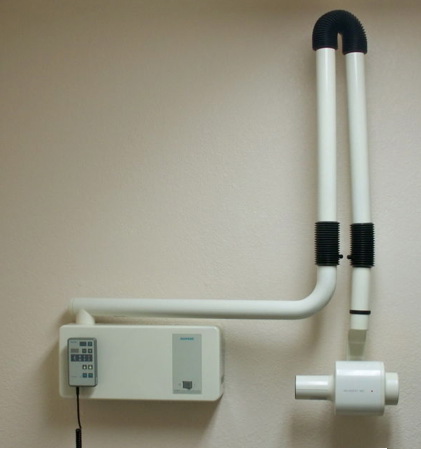
When programmed with firmware P2060X04, the A2060X controls a Siemens Heliodent x-ray source, part number 5938733D3195, designed for dental use. The photograph below shows one of these systems fully-assembled.
We have two of these machines. We removed the x-ray sources and discarded the arms. We damaged one of the x-ray sources by failing to switch it correctly (we failed to apply the setup signal before the activate signal). The other one is in an enclosure made of lead bricks with a hole in the front to let out the x-rays.
With a cable harness, we connect our A2060X to the remote control terminal block in the Heliodent power supply, which is labelled X2 on the silk screen. By closing the correct relays, we can set up the power supply, activate the x-ray head, and select 60 kV or 70 kV maximum energy. The A2060X has a six-way plug, J1 with pin numbers 1-6, and the Heliodent has a terminal block, X2, with terminals 1-6 as well as a few more for the AC line inputs. The following table gives the connections that we make with wires from the A2060X to the Heliodent.
| J1 Pin on A2060X | X2 Terminal on Heliodent |
|---|---|
| 1 | 2 |
| 2 | 3 |
| 3 | 1 |
| 4 | 5 |
| 5 | 1 |
| 6 | 6 |
For an account of experiments we performed with the Heliodent x-ray source see Pulsed Xrays and Dosimeters.
The A2060X is a LWDAQ device. The A2060X connects to the x-ray source with a six pin one-row header. The A2060X circuit and x-ray source remain isolated from one another, however, because we use relays on the A2060X to connect terminals in the x-ray source. The Dosimeter Instrument allows us to send instructions to the A2060X during x-ray exposure of radiation sensors. The A2060X turns on the x-ray source for a specific time in response to a single LWDAQ command.The following table gives the A2060X's use of the LWDAQ command bits.
| DC16 | DC15 | DC14 | DC13 | DC12 | DC11 | DC10 | DC9 | DC8 | DC7 | DC6 | DC5 | DC4 | DC3 | DC2 | DC1 |
|---|---|---|---|---|---|---|---|---|---|---|---|---|---|---|---|
| P7 | P6 | P5 | P4 | P3 | P2 | P1 | P0 | WAKE | LB | X | X | X | X | X | KV |
The KV bit selects 60 keV or 70 keV maximum x-ray energy. When set, the maximum energy is 70 keV. When clear, the maximum energy is 60 keV. The LB bit is loop-back for measuring the cable propagation delay, a standard LWDAQ diagnostic action. The WAKE bit is not used by the A2060X: the ±15V power is always applied to the relays.
To generate an x-ray pulse we write an eight-bit number to P7..P0. This number gives the length of the required pulse as a multiple of 10 ms. Thus 100 gives a pulse of 1 s. Upon receiving a fresh command, the A2060X asserts its SETUP output. A fraction of a second later it turns on the x-ray source with ACTIVATE. The SETUP output remains asserted for a fraction of a second after ACTIVATE is unasserted.
One function of the x-ray head is to stop the x-ray from over-heating. The A2060X firmware makes sure that the x-ray head cannot be turned on for more than a certain fraction of the time. In firmware version 4, this fraction is 1/32, so that we can have, for example, a 1-s exposure every thirty seconds. The A2060X uses a safety counter that counts up when the x-ray is on, and counts down when the x-ray is off. It counts down 32 time faster than it counts up. The A2060X will turn on the x-ray head only when the safety counter is less than a certain threshold.
The A2060X provides a total of 22 indicator lamps. Looking at the circuit board, the eight red lamps on the lower left are LED1-LED8 from bottom to top. The eight red lamps on the upper left are LED9-LED16. The upper two on the right are the ±15V indicators. The lower four are TP1..TP4 from bottom to top. The following table gives their meanings.
| Lamp | Meaning |
|---|---|
| LED1 | SETUP asserted to x-ray source |
| LED2 | ACTIVATE asserted to x-ray source |
| LED3 | KV asserted to select 70-keV energy |
| LED4 | PCK, pusle clock, 100 Hz square wave |
| LED5 | NCS, new command strobe |
| LED6-7 | not used |
| LED8-16 | SC0..SC8 respectively, safety counter |
| TP1 | start exposure state |
| TP2 | setup before activate |
| TP3 | activate x-ray source |
| TP4 | setuup after activate |
The ±15V power indicators should always be on when the board is plugged into the LWDAQ.