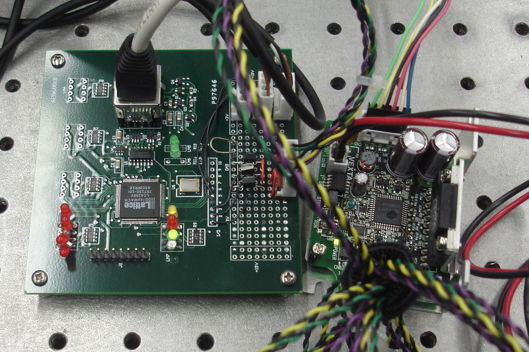
The A2060M is a Stage Controller extension for the Programmable Logic Head (A2060). We built this version for our 300-mm motorized stage. The stage consists of the A2060M, a CMD2120P motor driver, a CMK264MAP microstep stepper motor, a 24-V power supply, and an LSA3-300-B02-X linear drive stage.

The A2060M uses the LC4256V-10T100I programmable logic chip to produce pulses for the motor driver and to monitor the limit switches. The three connections to the motor driver are open-drain outputs. The three limit switches connections are a combination of +5V power for the limit switch light source and an open-collector opto-isolator output. The motor driver takes the pulses and applies power to the stepper motor windings so as to move clockwise or anti-clockwise. The A2060M logic implements acceleration and decceleration for long moves of the stage. The stage does not miss steps on long moves, but it does vibrate at the center of its range when there is no load applied to the movement. We manage movements of the motor through the A2060M with our Stage Controller Script, which runs in the LWDAQ Toolmaker.
The A2060M is a LWDAQ device. It obtains power for its internal logic from the LWDAQ, but motor power must be delivered by a separate positive power supply, which we connect to the motor driver.
| DC16 | DC15 | DC14 | DC13 | DC12 | DC11 | DC10 | DC9 | DC8 | DC7 | DC6 | DC5 | DC4 | DC3 | DC2 | DC1 |
|---|---|---|---|---|---|---|---|---|---|---|---|---|---|---|---|
| D7 | D6 | D5 | D4 | D3 | D2 | D1 | D0 | WAKE | LB | ECHI | DTX | ECLO | !ACD | DIR | RUN |
The D6..D0 bits set the pulse end count high and low bytes, in conjunction with ECHI and ECLO. The DIR bit sets the direction. Clockwise is HI. The DTX bit enables read-back of the limit switches and movement status. We use the data device read job to get a byte from the A2060M into driver memory. See the Stage Controller Script for code to do this. The byte we get back has eight bits with the following meanings, from least significant to most significant: RUN, DIR, STOP, UP, CENTER, LOW, HIGH. The STOP bit indicates that the end count has been reached: all pulses have been transmitted. The UP bit indicates that the motor is accelerating or at full speed. The CENTER bit indicates that the center limit switch is closed. The LOW bit indicates that the limit switch closest to the motor is closed. The HIGH bit indicates the limit switch farthest from the motor is closed.
The ACD bit is Auto Current Down. When we set this bit HI, the motor will be supplied with full current when stationary. When low, the motor will be given less current when stationary.
Limit Switch Connections: Sketch of color coding and pinout for limit switch connections.
Firmware: Various versions of the firmware. All versions include a command receiver.
ispMACH4000: Data sheet for the programmable logic chip.
Programming Instructions: How to program the logic chip on another of our circuits.