 ICX424 Minimal Head (A2076) Manual
© 2012-2021 Kevan Hashemi, Brandeis University© 2021-2025 Kevan Hashemi, Open Source Instruments Inc.
© 2018 Mihir Khanna, Brandeis University
[25-MAY-22] The ICX424 Minimal Head (A2076) holds a single ICX424 image sensor and an optional two or four illumination LEDs. Power and drive signals enter the circuit board through a twelve-way flex connector. Three capacitors provide local de-coupling of the supplies. The image sensor output is routed directly to the connector without buffering. The A2076 operates in conjunction with IXC424 drive board such as the Camera Head (A2075), H-BCAM Head (A3025), N-BCAM Head (A2083), and D-BCAM Head (A2086). The A2076 will accommodate both the monochrome (IXC424AL) and color mosaic (IXC424AQ) versions of the image sensor. For a detailed discussion of these sensors see the A2075 Manual.

The following versions of the A2076 exist.
| Version | Description |
|---|---|
| A2076A | ICX424AL monochrome, CMT821 footprint, Laboratory Camera (A2075B) |
| A2076B | ICX424AQ color, CMT821 footprint, for Laboratory Camera (A2075C) |
| A2076C | ICX424AL monochrome, two red LEDs, for LGT Camera (A2075D) |
| A2076D | ICX424AL monochrome, no LEDs, for Black H-BCAM (A3025). |
| A2076E | ICX424AL monochrome, no LEDs, for Blue H-BCAM (A3025). |
| A2076F | ICX424AL monochrome, no LEDs, for nSW Bar Head (A2082). |
| A2076G | ICX424AL monochrome, four LEDs, for BIS7/8 Head (A2082). |
| A2076H | Dual ICX424AL monochrome, connector for two LEDs. |
| A2076I | Dual ICX424AL monochrome, connector for two LEDs. |
| A2076J | ICX424AL monochrome, for Black and Blue D-BCAM (A2086L/R). |
The A2076A and A2076B use the same circuit board, the A207601A, but are equipped with the ICX424AL monochrome and ICX424AQ color mosaic image sensors respectively. The board provides mounting holes on each corner, as well as two mounting holes for a lens holder. The lens holder accepts any lens assembly with an M12, 0.5-mm pitch thread.

The A2076C, shown below, provides two LEDs in 3-mm radial packages for illumination of the field of view. As shown in the circuit diagram, the LEDs are connected in series to +15V. We can either provide a permanent path to 0V through resistor R1, or we can connect power to the LEDs using the L signal on J1-11. In the circuit shown below, we use R1 to provide power whenever +15V is connected to the circuit.

Although we designed the A2076 to work with the ICX424AL and ICX424AQ image sensors, the larger ICX204AL and ICX204AK image sensors are also, in theory, compatible with the A2076. These sensors are monochrome and color mosaic respectively, provide the same image area, but with an array of 1034 × 779 pixels.

The A2076 can provide two or four LEDs for illumination. The four-LED circuit uses a mosfet and resistor to provide power to LEDs in response to a logic HI on L, as shown in S2076_2.gif. The two-LED circuit turns on both LEDs through R1 whenever +15V power is supplied, or if R1 is omitted, it turns on the two LEDs when L is connected to zero in an external circuit. With LED1 and LED2 installed and a 0.5-W 47-Ω resistor in place of R1, the lamps will shine whenever the image sensor has power. With LED1 and LED2 installed, but R1 omitted, the lamps will turn on only when the L control input draws current out of them.


The A2076D and A2076E are for the Black and Blue HBCAM respectively. In the HBCAM, these boards connect to the A3025L and A3025R respectively. With the image sensor pin 1 in the top left of both images, we note that the flex connectors are inverted. But both versions can connect to either the A3025L or A3025R. The A2076J is the first version of the A2076 in which the image sensor can be pushed all the way into its footprint to sit flush with the printed circuit board.


The A2076J differs from its predecessors in two ways. First, the hole for pin 1 on the ICX424 CCD has been widened from from 25 mils (0.62 mm) to 30 mils (0.75 mm). Second, the 12-way flex socket is now a surface mounted connector. The consequence of these two modifications is that we can push the CCD package all the way into its footprint until it is flush with the PCB. In earlier versions, the slightly wider pin 1 on the CCD would not fit all the way in the hole, and the pins from the through-hole flex socket emerging under the CCD kept the CCD away from the board surface.
Connect the A2076 to a ICX424 read-out device such as the Camera Head (A2075). Make the connection with a 12-way, 1-mm pitch flex cable. The connector on the A2076 can be one with contacts only on one side of the flex cable or upon both sides. Flex cables and connectors are not polarised, so it is easy to plug the cable in the wrong way. If the connector has contacts on both sides, the power and drive signals will be delivered to the A2076 in reverse order. But the pinout of the connector is chosen to make it tolerant of a reversal of the cable. Thus we can plug the cable in one way, see if the sensor works, then switch it around, without fear of damaging the circuit.
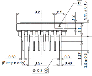
In order to interpret the geometry of the acquired image in terms of the image sensor surface, you will need to locate pin one of the image sensor package, and consult Image Geometry in the A2075 manual. Finding pin one on the image sensor package is best done by looking for the pin with the thicker base, as shown below.

Because the cable carries the output signal back to the drive board without buffering, we expect to see image noise increasing with the length of the flex cable. Cross-talk between the clock signals and the pixel intensity will be synchronous, so we do not expect this source of noise to be significant. But pick-up of external interference will increase with cable length. The vertical clock signals have at least 7 μs to settle after each transition, because they are controlled by LWDAQ command transmissions to the drive board. Thus we doubt that flex cables of up to 50 cm will have any effect upon their transmission to the image sensor. The horizontal clock signals are far faster and more likely to distort. We allow 500 ns for each correlated double-sample of the output, and hope that the 5-V horizontal clock signals settle within 50 ns of a transition. Nevertheless, the clock signals should propagate down a 50-cm flex cable in only 2.5 ns, so we do not expect reflections at the cable ends to cause significant problems.
The A2076 provides two LEDs in series for illumination. These can be powered continuously through resistor R1, if present, or controlled through the L connection on J1-11. Because the ICX424 provides instant clearing and readout with its clearing and readout pulses, there is no need for us to synchronise the flashing of these lights with the clearing, exposure, and readout of the image sensor. Thus it is feasable to use the image sensor with continuous illumination. When we use the A2076C with the A2075, for example, the LEDs turn on whenever the A2075 wakes up.
The A2076C together with the A2075C are the first ICX424 circuits designed specifically for application in ATLAS at CERN. Four A2076Cs mounted on a prototype Long Guide Tube. The LGTQC script reads out all four cameras through a multipexer and displays their images in one window. The images can be read out with high resolution or low resolution. They appear the same size regardless, but the low resolution readout is four times faster.
Note: All our schematics and Gerber files are distributed under the GNU General Public License.
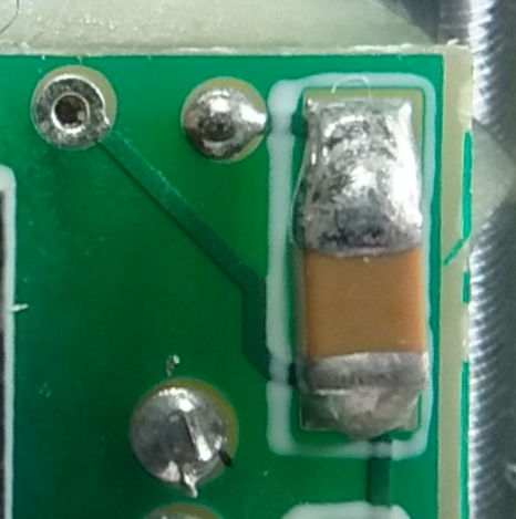
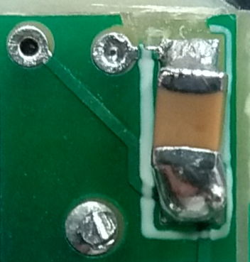
S2076_1: Sensor Connection and Dual LED Extension[13-MAR-19] We have an A2076F returned from Freiburg University. They noted, and we confirm, that +15V is shorted to the aluminum frame into which the A2076F has been glued for mounting into an alignment bar disk. The short between +15V and the frame occurs at the via shown below.


After we remove the excess solder from the via, the short no longer exists. If there is one such solder spike, there are likely to be others. They could form on any of the vias. so that's signals V1, VL, H2, S and voltage levels +15V and 0V. Thus we can expect a variety of symptoms when we connect the alignment bar to our 0V voltage level. If we connect the bar to 0V during testing, it won't work taking images when there is a short on any of these signals and levels, with the exception of a short to 0V, which we will have to detect with an isolated bar and a resistance meter.