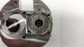
Figure: Proper Orientation of CCD Bracket. Note the 90° corner facing up and out.
| Mask Station | Lens Station | CCD Station | Center Station |
| Station Distances | Tolerance of Station Placement | Wiring | L-Boards | RTD Attachment | U-Channel |
| Device Elements | Burn-In Acquisifier Script | Sample Result |
Each bar nSW alignment system (assembly drawing here) consists of four lines consisting of a rear-lit rasnik mask, a focusing lens, and an ICX-424 CCD. The four lines are set up on seven stations, labeled A-G. Control electronics are on the center station. A board connecting the shield of the root cable to the bar is attached to the near end cap.
Mask stations (drawing) consist of a glass Rasnik mask, a diffuser, and a circuit board with nine royal blue Luxeon Z light-emitting diodes. Aluminum frames hold each part at a fixed distance and the entire assembly is epoxied to the station frame. When looking down at the station, with the masks facing up, the mask on the left (long line) should be square size 170 um, and the mask on the right (short line) should be square size 120 um.
Lens stations (drawing) require only the epoxying of the single 220-mm focal length lens into the station housing. The lens rests on a small ledge should be inserted such that the flat side rests against the aluminum. Only a few small dots of epoxy around the outside of the ledge are required to hold the lens in place.
CCD stations (drawing) consist of a main station housing, a 300-mm focal length lens, and two attachments for mounting CCDs. The lens is epoxied in first in the same manner as the lens station.
The CCDs are epoxied into the attachment brackets such that the circuitboard (A207601F, image here) rests inside the recess facing outward. There is no handedness to the circuitboard, and it is installed in both brackets the same way. It will be apparent if the circuitboard is installed upside down, as it will only rest flat in the attachment in the proper orientation.
After the epoxy has dried, attach a 2" (5.1 cm), 12-pin Flat Flexible Cable (often FFC or FLEX-12) into the connector. It is difficult to insert the cable after the bracket is attached to the station assembly.
The brackets have a handedness, as there are three notched corners and one sharp corner on each bracket. They should be installed such that the sharp corner is facing up and out from the center of the station, with the CCD facing out. A collimator is then installed on the outside of the bracket with two pan head screws.
Note: Spare alignment bars may not have collimators included, so anyone replacing an alignment bar setup should salvage the collimators before shipping the damaged parts back to Brandeis.

Center stations (drawing) require no epoxy and are purely mechanical assembly. Orient the circuit board so that the SW06 analog switch (U12) matches up with the recessed groove in the mounting plate. Once the board is mounted, attach the polymer cable guides to the ends of the mounting plate.
| Station | Label | Dist. (mm) from inner end | Loc. of Optical Element |
|---|---|---|---|
| Near End Cap | none | 0 | N/A |
| Near Mask | A | 54 | 68 |
| Near Lens | B | 478 | 478 |
| Near CCD | C | 950.5 | 940/961 |
| Center | D | 1179 | N/A |
| Far CCD | E | 1407.5 | 1397/1418 |
| Far Lens | F | 1880 | 1880 |
| Far Mask | G | 2304 | 2290 |
| Far End Cap | None | 2382 | N/A |
The placement of the stations is determined by the focal length of the lens. Magnification is not a controlled parameter, so we take the best possible image. We find minimal variance in the focal length of the lenses, so we decide to make all bar placements identical and symmetrical. CCD station displacement leads to image deterioration after 2 mm. Lens station placement is sensitive to +/- 20 mm, so we place it at the midpoint of the short line for simplicity. Because the lens stations are sensitive to displacement of 2 mm, we recommend that the stations be placed with ~1 mm precision.
Wiring color coding is the same on both sides of the Bar Head. RTD pinouts are reversed; when looking at the Bar Head, the yellow cable should be closest to the top. LED Mask Cables should be interchangeable between the near and far sides. RTD and mask connections are terminated in non-reversible plugs.
The LWDAQ cable is 1180 mm in length. It is jacketless and unshielded. Construction of these cables follows the LWDAQ Cable-Making Guide for white cables, excepting the lack of a shield cable and load bar.
| Wire | Length (mm) | Color | |
|---|---|---|---|
| Positive (pin) | Negative (pin) | ||
| LWDAQ | 1180 | Various | |
| RTD, Mask | 1230 | Yellow (top) | White/Yellow (2nd) |
| RTD, CCD | 310 | Blue (3rd) | White/Blue (bottom) |
| LED, Short Line | 1190 | Brown (4) | White/Brown (3) |
| LED, Long Line | 1190 | Green (2) | White/Green (1) |
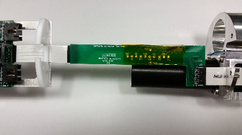
The A208202B is an extension arm for the Bar Head camera cables. It has several test points on either, which should be covered with a wrap of Kapton (or equivalent) non-conductive tape. The placemnet of the connectors on the L-Board is compatible with the CCD station and can be used to ensure that the CCD stations are mounted in the proper orientation. The L-Board is attached to the Bar Head and the CCD heads by 2" (5.08 mm) FLEX-12 cables.
RTDs are attached on the outer sides of mask and CCD stations. Cables are run to the outer sides of the stations and passed through the station twice for strain relief. The RTDs are superglued to a small piece of Kapton tape. The tape is trimmed with a razor blade. Wires are soldered to the exposed ends of the RTDs. (Wires can be attached before or after the RTD is in place.) DP-460 epoxy is used to cover the entire tape area, attaching the RTD securely to the aluminum station. Thermal contact is maintained through the Kapton tape to the face of the RTD.
The U-Channel aluminum pieces used by Brandeis to build mock-ups of the alignment bars are 1060 mm long. 170 mm away from the inner end of the U-channel is a notch approximately 1 mm wide cut halfway through the channel. This allows the blue and white/blue Mask RTD wires to pass through the channel and down to the station. No other nothces are required. Care should be taken to prevent machined edges of the notch and U-channel ends from cutting into the wires. Burrs should be removed with a file or deburring tool.
| Line | CCD Device Element | Source Device Element |
|---|---|---|
| Near Mask, Long Line | 1 | 3 |
| Near Mask, Short Line | 4 | 4 |
| Far Mask, Long Line | 3 | 1 |
| Far Mask, Short Line | 2 | 2 |
The Acquisifier script used to burn in the In-Bar Assembly can be found here. We run each setup for 24 hours and record data every five minutes; we have yet to observe any intermittent or permanent failure.
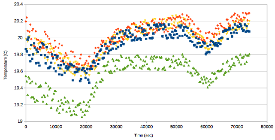
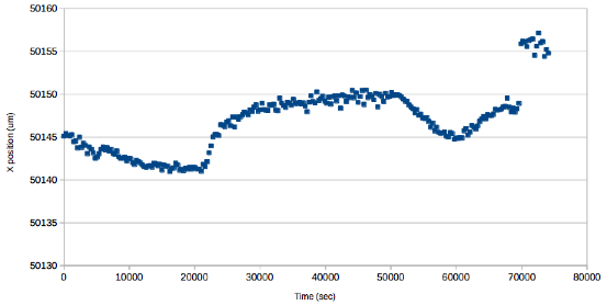
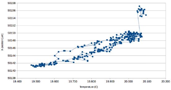
We record the burn-in of "Bar #33", which we expect to be used as a spare. We plot the following charts:
