Timing and Control Module (A2101)
© 2008-2012, Kevan Hashemi, Brandeis University
Contents
Introduction
Setup
Performance
To Do
Electronics
Introduction
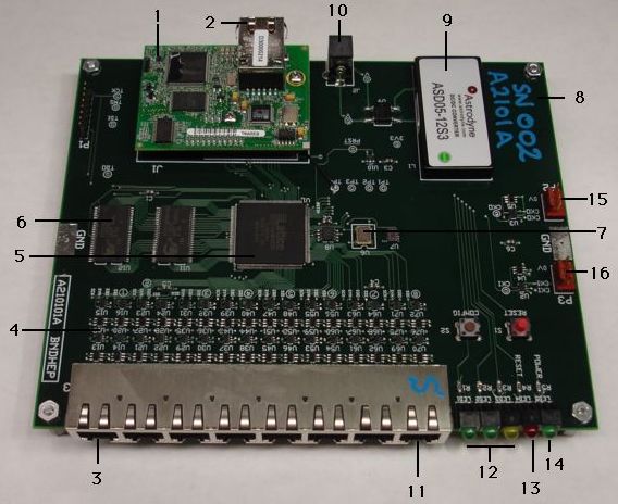
The Timing and Control Module (TCM) is part of the proposed LSST camera. We describe its purpose and operation in our TCM Specification. The A2101A is a prototype TCM designed for use in test stands. It provides one RJ-45 socket for Ethernet connection, seven RJ-45 sockets for connection to RCMs (Raft Control Modules), and one RJ-45 socket that can act like an RCM. The A2101A is the prototype Timing and Control Module. The A2101X is the RCM-Emmulator. We use the A2101X to test the A2101A.

Figure: Timing and Control Module (A2101). Marked are (1) RCM4200, (2) 100-Base-T ethernet socket, (3) eight-way RJ-45 connection with Socket 1 on the left, (4) LVDS transceivers and clamps, (5) programmable logic, (6) one of two 2-MByte SRAMs, (7) 50 MHz crystal oscillator, (8) Mother-Board, (9) DC-DC Converter, (10) power jack, (11) Complimentary LVDS transceivers, (12) programmable indicator lamps, (13) reset indicator, (14) power indicator, (15) clock output, and (16) external clock input. Sockets 1-7 are master sockets for communication with RCMs. Socket 8 is a slave socket for use with the RCM-Emmulator firmware.
The receives DC power through a single power jack. The DC voltage can be anything from 9V to 36V. An internal bridge rectifier corrects the polarity of the voltage on the connector.
We delivered an A2101A and its opposite, the A2101X, to Harvard University in early 2009. In 2010, our former colleage Michael Bradshaw used the open-source A2101A design and software as the basis for an ASIC test board, as he describes in Customizable ASIC Test Stand.
Setup
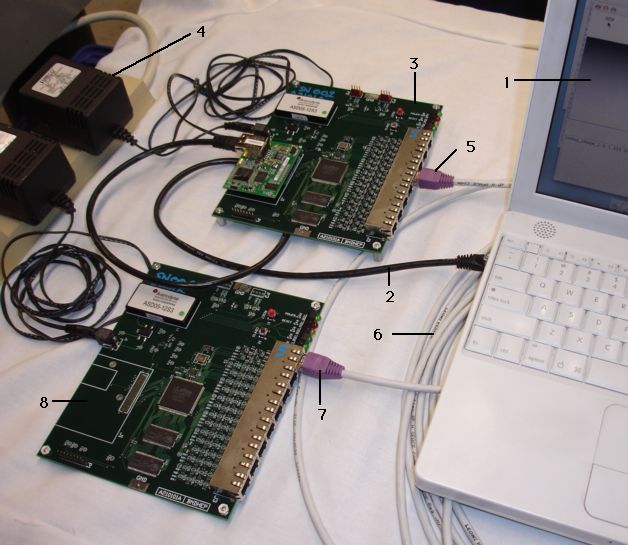
The figure below shows a Timing and Control Module (A2101A) connected to a single RCM Emmulator (A2101X).

Figure: TCM Setup. Marked are (1) laptop acting as a TCPIP client to the TCM, showing image retrieved from RCM Emmulator, (2) ethernet cable, (3) TCM, (4) power adaptor, (5) connection to TCM Socket 5, (6) ten-meter network cable, (7) connection to RCM Emmulator slave socket, and (8) RCM Emmulator.
To set up and operate the above system, follow the following steps.
Download our LWDAQ Software from here. Follow the installation instructions in our LWDAQ User Manual. Run the software.
Plug power into the TCM (A2101A). Connect your laptop and the TCM with an ethernet cable. Set up your laptop to use its ethernet socket for connections to subnet 10.0.0.x. Look at the RCM4200 module. Are the yellow and green ethernet lights turning on? If not, check your cable and your laptop's ethernet configuration.
Select Configurator from the LWDAQ Tool Menu. For instructions on using the Configurator, see the LWDAQ User Manual. Enter 10.0.0.37 for the IP address and 90 for the port number. Press Contact to see if you can contact the TCM. If you cannot make contact, reset the TCM's EEPROM configuration by pressing the red reset button and the brown configuration button at the same time, releasing the reset button, and continuing to hold down the configuration button for another five seconds. Try to make contact again.
Plug power into the RCM Emmulator (A2101X). You should see the power light come on. Press the reset button. The red light should turn on. Connect the socket marked S on the RCM Emmulator to one of the sockets that is not marked S on the TCM. Use a shielded CAT-5 network cable. You should see one of the green lights on the RCM Emmmulator turn on as the RCM Emmulator receives a clock signal.
NOTE: Be sure to use a shielded ethernet cable to connect the A2101A to an RCM or A2101X. The shield provides a ground connection between the two circuits. Without the ground connection, we found the communication would be reliable one day and fail intermittently the next. When the ground potentials of the two circuits differ by more than a few volts, the LVDS communication fails.
Download our selection of sample scripts and save it to disk. Click here to download the A2101.tcl scripts file. Open the LWDAQ Toolmaker. You can read about the Toolmaker in the LWDAQ User Manual. Press the Toolmaker's Load button and load the A2101.tcl into the Toolmaker. Alternatively, you can open A2101.tcl with a text editor and cut and paste scripts from the file into the toolmaker. Don't cut more than two sample scripts at a time, and leave out the script tags.
Work your way through the sample scripts. The first one tests the TCM's echo instruction. The last one writes and reads back a 4-MByte test image from the RCM Emmulator. We have tried to put plenty of comments into the scripts so you can see how the TCL code calls our LWDAQ routines to communicate with the TCM and control the RCM Emmulator.
If you would like to put the TCM on your local ethernet with a static IP address, follow the instructions in the Configurator section of the LWDAQ User Manual.
Try alternating between a short and a long cable from the TCM to the RCM Emmulator. You should see no affect upon the accuracy of the communication nor the speed with which the communication takes place. At some point, communication will fail because of dispersion in the twisted pair. We estimate that this will take place at around 50 m.
One of the sample scripts in A2101.tcl creates a 4-MByte gray-scale image in the TCM's RAM, transfers it to the RCM Emmulator, and reads the image all the way back to the TCPIP client. With a direct connection between the TCPIP client and the TCM, we obtain 600 kBytes/s through the RCM4200 and 4 MBytes/s over the TCM-RCM serial connection. When we receive TCPIP messages with the A2101, parse them, and execute byte reads from registers on the mother board, the message execution time is 130 μs.
Note: When we were planning the design of the TCM, we considered using a PC104-format Linux computer to provide TCPIP connection. But we found that the PC104 computer, combined with standard digital I/O boards, did not allow us to manipulate digital I/O lines with sufficient speed for the kind of external memory access required by the TCM. In an un-modified PC104 system, our fastest I/O line update time was 5 μs with a dedicated program that did nothing but toggle the logic line, as we describe here. The RCM4200 offers us far superior performance. We transfer data from the A2101A SRAM by with the RCM4200 digital I/O ports. We fetch one byte at a time. Each byte transfer takes 400 ns. The digital I/O update time is around 100 ns, which is fifty times faster than that of the PC104 module we tried.
The RCM4200 consumes around 240 mA at 3.3 V, for a total power consumption of less than 1 W. The entire A2101A consumes 94 mA from our 24-V power supply, for a total consumption of 2.4 W.
The serial communication between the TCM and the RCM Emmulator can pass along a cable of at least ten meters, and probably 50 m.
To Do
When we have time, we hope to add the following features.
- Pressing CONFIG switch on an A2101X causes the device to abort any current communication and send an error message to its master. In P2101X02.abl, the CONFIG switch does nothing.
- The A2101X should be able to run off its own clock and switch automatically to the master's clock when available. In P2101X02.abl, the device always uses the master's clock.
- The A2101A should support communication with the slave's auxilliary device over the SAO signal (TCM jobs aux_read, aux_write, etc.).
- The A2101X should respond to communication over SAO.
- The A2101A should switch to an externally-supplied clock from P3 when present.
Electronics
Note: All our schematics and Gerber files are distributed under the GNU General Public License.
Code
C2037E13.c: SIAP/LWDAQ Server source code for RCM4200.
C2101A13.bin: SIAP/LWDAQ executable for RCM4200 (zip archive).
C2037E14.c: LWDAQ-Only source code for RCM4200.
C2101A14.bin: LWDAQ-Only executable for RCM4200.
P2101A05.abl: Logic source code for U1 on A2101A.
P2101A05.jed: Logic program for U1 on A2101A.
P2101X03.abl: Logic source code for U1 on A2101X.
P2101X03.jed: Logic program for U1 on A2101X.
A2101.tcl: Library of test routines.
Schematic
S2101_1 RCM4200 Interface
S2101_2 Clock Generator
S2101_3 RAM
S2101_4 Power
S2101_5 RCM Socket 1
S2101_6 RCM Socket 2
S2101_7 RCM Socket 3
S2101_8 RCM Socket 4
S2101_9 RCM Socket 5
S2101_10 RCM Socket 6
S2101_11 RCM Socket 7
S2101_12 RCM Socket 8
PCB
A210101A For A2101A.
Assembly
A210101A.bom Bill of Materials for A2101A.
Modifications
The A210101A printed circuit board must be modified in the following ways for it to be consistent with the A2101A schematic.
- Cut track from J1-24 to P1-6 and U1-91. This stops PC0 on the RCM4200 from driving TMS on U1.
- Cut track from J1-25 to P1-8 and U1-41. This stops PC1 on the RCM4200 from driving TCK on U1.
- Cut track from J1-26 to P1-3 and U1-3. This stops PC2 on the RCM4200 from driving TDI on U1.
- Cut track from J1-27 to P1-2 and U1-129. This stops PC3 on the RCM4200 from driving TDO on U1.
- Connect J1-38 to U1-24 using the TP4 pad. This connects PE6 of RCM4200 to DS on U1.

