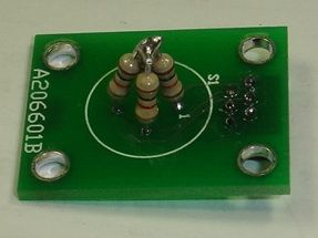
| Schematic | PCB | Assembly |
The Inclinometer Head (A2065) is a Long-Wire Data Acquisition (LWDAQ) Device that reads out a liquid-level tilt sensor. The sensor is on a second circuit board, called the Inclinometer Sensor Head (A2066). The sensor that mounts on the A2066A is a five-pin liquid level, part number 59560 from Applied Geomechanics. We present the accuracy and precision of the A2065 in our Inclinometer Performance report. We use the A2065 with the LWDAQ Software's Inclinometer Instrument. For links to all Inclinometer documentation, go to the Inclinometer Home Page.

The following versions of the A2065 exist.
| Version | Description |
|---|---|
| A2065A | Prototype used in initial studies. |
| A2065B | ATLAS Version |
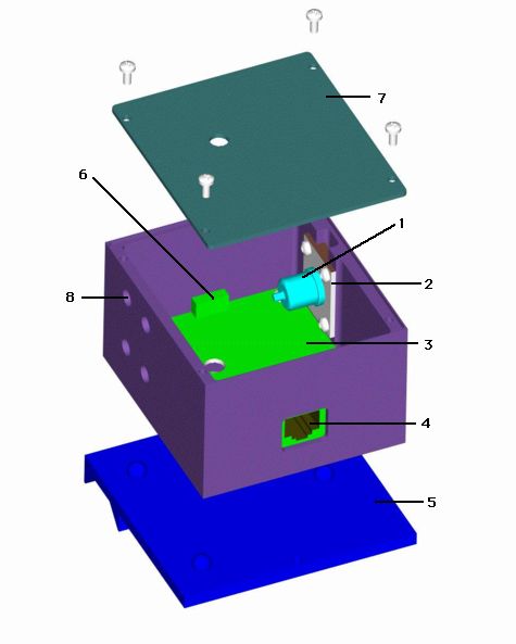
The A2065 drives its liquid-level tilt sensor with a sine wave of frequency 1.1703 kHz, which is 32.768 kHz divided by twenty-eight. Below is a drawing of the A2065B showing its mounting plate and lid.

The A2065B uses the A206501C printed circuit board. For hole and connector locations on the A206501C, see here.
The A2065 is complies with the LWDAQ Specification, except in its power consumption. The A2065 consumes 11 mA from the +5V supply when it is asleep, which exceeds the 5 mA limit set by the LWDAQ Specification.
| State | +15 V | -15 V | +5 V |
|---|---|---|---|
| Asleep | 7 mA | 6 mA | 11 mA |
| Awake | 7 mA | 6 mA | 11 mA |
The A2065 is LWDAQ Device type 0 for device-dependent jobs. It has no device elements for device-dependent jobs. Its command bit allocation is as follows.
| DC16 | DC15 | DC14 | DC13 | DC12 | DC11 | DC10 | DC9 | DC8 | DC7 | DC6 | DC5 | DC4 | DC3 | DC2 | DC1 |
|---|---|---|---|---|---|---|---|---|---|---|---|---|---|---|---|
| X | X | X | X | X | X | X | X | WAKE | LB | X | !DY | !DX | S2 | S1 | S0 |
When the A2065B is asleep, its sin wave drives the sensor so that the sensor will be ready for immediate read-out. If we disconnect the sensor between measurements, some of the AC coupling capacitors discharge, and add an offset voltage to the returned signals. This offset voltage can be sufficient to put the signal outside the dynamic range of the LWDAQ driver's ADC.
| [S2..S0] | Signal |
|---|---|
| 0 | VCOM (signal reference voltage) |
| 1 | 0V (circuit zero-volt supply) |
| 2 | SIN (the sin wave) |
| 3 | CTR (center electrode of sensor) |
| 4 | X+ (X+ electrode of sensor) |
| 5 | X- (X- electrode of sensor) |
| 6 | Y+ (Y+ electrode of sensor) |
| 7 | Y- (Y- electrode of sensor) |
The Inclinometer Instrument selects the inclinometer signals in turn. It measures the sinusoidal amplitude of each. It subtracts and divides these amplitudes to obtain two fractions between 0 and 1, which we denote X and Y. Both X and Y are nominally 0.5 when the tilt sensor is horizontal. The slope of X and Y with inclination in their respective directions is 413 μV/V/mrad for the two-dimensional, glass, 59560D sensor (see here). The slope of X is roughly 6600 μV/V/mrad for the one-dimensional, ceramic 59577 sensor (see here).
The liquid level sensors are affected by temperature, with a change in apparant inclination of order 125 μrad/°C for the 59560D sensor (see here). These same sensors are unaffected by magnetic fields less than 100 mT (see here). When we first set up a 59560D sensor, we can expect its measurement to drift by up to 3 mrad during the first 100 hours (see here). Resolution from one measurement to the next is around 60 μrad.
We read out the A2065B with the Inclinometer Instrument in our LWDAQ Software. The Inclinometer Instrument instructs the A2065 to apply a sine wave across the X+/X− terminals of a tilt sensor, and then the Y+/Y− terminals. The Inclinometer calculates the amplitude of the n'th harmonic of each recorded waveform, where n is the value of config(analysis_harmonic) in the Inclinometer window.

When it measures X-direction tilt, the Inclinometer drives the X+/X− terminals of the sensor. In the A2065B, X+ is connnected to the sine wave, and X− is connected to VCOM. The sine wave is centered upon VCOM, so the net DC voltage applied to the sensor is zero. Even if the sine wave were not centered upon VCOM, capacitors in series with ever tilt sensor electrode prevent any DC current flow into the sensor. The Inclinometer Instrument records the signal on X+ and the sensor's center electrode, which we call CTR. It calculates the ratio of the amplitude on CTR to the amplitude on X+. We call this ratio X.
Aside: When we first started working with the A2065B, we monitored X− as well, on the grounds that there is a slight voltage drop across the X− coupling capacitor. But our long-term studies showed that we gained nothing from using X−, and lost some resolution because of added noise.
When it measures the Y-direction inclination, the Inclinometer Instrument drives the Y+/Y− terminals of the sensor, and determines the ratio of the resistance between CTR and Y− to the resistance between Y+ and Y−. We call this ratio Y. The Inclinometer Instrument result is a string containing the amplitudes of four sinusoids, followed by X and Y. We obtain this result in Tcl code with the command "LWDAQ_acquire Inclinometer", having configured the Inclinometer Instrument to acquire a measurement from our A2065 and sensor.
| Name | Index | Description |
|---|---|---|
| Source | 0 | Name of the image or file containing measurements. |
| X+ | 1 | Amplitude of sinusoid on X+ during X-measurement. |
| XCTR | 2 | Amplitude of sinusoid on CTR during X-measurement. |
| Y+ | 3 | Amplitude of sinusoid on Y+ during Y-measurement. |
| YCTR | 4 | Amplitude of sinusoid on CTR during Y-measurement. |
| X | 5 | XCTR / X+ |
| Y | 6 | YCTR / Y+ |
The X and Y fractions will be close to 0.5 when the sensor is horizontal. The slope of X and Y with inclination depends upon the sensor we use with the A2065. In the case of the 59560D glass sensor, the slope is 413 μV/V/mrad. Thus a change of 0.000413 the X fraction indicates a rotation of 1 mrad in the x-direction (413 μV/V per mrad).
We use the LWDAQ Driver's (A2037) delay timer and repeat counter, plus the fact that we can digitize any integer number of periods of the sinusoid, to make sure that our sampled version of the waveform contains a whole number of periods of the sine wave we apply to the tilt sensor. The period of this sine wave is 854.50 μs. The A2065 obtains the 1.170-kHz frequency by dividing a its 32.768-kHz reference by 28. It turns a 1.170-kHz square wave into a sine wave by passing it through a 1-kHz low-pass filter (U7 in the schematic, for more on filters see our Filter Design Guide).
The Inclinometer Instrument records sine waves with the LWDAQ Driver's eight-bit ADC. To obtain an accurate measurement of the amplitude of each sine wave, we must be sure that we record a whole number of periods. In the A2037E driver, the eight-bit ADC sampling job takes 500 ns. We can add to this daq_delay_ticks 125-ns delay ticks. We take daq_num_samples samples.
Example: We set the delay timer to 28, and execute the 500-ns Eight-Bit ADC Job 3418 times to obtain samples spanning a 13.672-ms interval, which contains exactly 16 periods of 854.50 μs.
Example: We set the delay timer to 4, and execute the 500-ns Eight-Bit ADC Job 1709 times to obtain samples spanning a 1.709-ms interval, which contains exactly 2 periods of 854.50 μs.
Example: We set the delay timer to 12, and execute the 500-ns Eight-Bit ADC Job 6836 times to obtain samples spanning a 13.672-ms interval, which contains exactly 16 periods of 854.50 μs.
We use our dummy sensor, made out of resistors, to test the inherent resolution of the A2065, as we describe elsewhere.

We obtain our best performance with more samples and more complete periods of the sine wave. The default Inclinometer settings are 6836 samples over 16 periods. With the dummy sensor we obtain a resolution of better than 100 μV/V for the X and Y ratios.
You will find the A2065 data acquisition steps layed out in detail in Inclinometer.tcl, the Tcl script that defines the Inclinometer Instrument in our LWDAQ Software.
There is a danger that the reference sinusoids will be too large, and so end up being clipped by the LWDAQ driver's ADC, as shown below.

When the reference waveforms are clipped off at the top, as shown above, the clipping introduces an apparant tilt in the sensor. If you see such clipping, your A2065B needs to be corrected, so as to reduce the amplitude of its sinusoids. In the case of the circuit that gave the waveforms you see above, we replaces the 330-Ω R5 with a 470-Ω resistor (schematic)
Note: All our schematics and Gerber files are distributed under the GNU General Public License.