| Schematic | PCB |
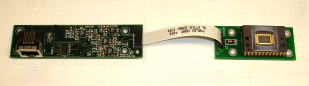
The KAF-0400 Head is a LWDAQ device that provides clock signals for a KAF-0400 Sensor Head (A2063). The sensor head holds a single CCD image sensor of type KAF-0400, KAF-0401, KAF-0402, or KAF-0261.

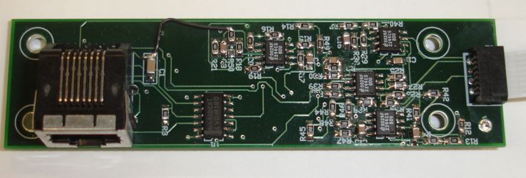
The A2061A provides a LWDAQ device socket in the form of a right-angle, shielded RJ-45. Connection to the A2063 is via the eight-way flex socket on the right side of the figure. For a bottom view of the board, see here.
The KAF-0400 was the first version of Kodak's 768×512 pixel full-frame CCD. (Note that Kodak's image sensor division is now Truesense Imaging Inc, a subsiduary of ON Semiconductor.) The KAF-0400 was replaced by the KAF-0401E, which in turn was replaced by the KAF-0402. These sensors are pin-compatible, and we find that, despite slight differences in their specifications, they are interchangeable. They have 9μm square pixels and provide an active area 6.9 mm × 4.6 mm.
The image we obtain with the LWDAQ, contains 800 columns and 520 rows. Within this image, we recommend analysis boundaries 20, 8, 784, and 516 for left, top, right, and bottom edges respectively. These boundaries will enclouse only the active image pixels. The top rows tend to be filled with residual charge when the sensor is exposed to bright light, so we prefer to omit rows 0-7 from our analysis bounds.
| Version | Description |
|---|---|
| A | KAF-0400 Head (original board, hard to assemble, reads KAF-0400, KAF-0401E, KAF-0402) |
| B | KAF-0400 Head (fits in PPL enclosure, reads KAF-0400, KAF-0401E, KAF-0402, uses P206101D PCB) |
| C | KAF-0261 Head (fits in PPL enclosure, reads KAF-0261, uses P206101D PCB) |
The A2061A and A2061B are compatible with the KAF-0400 Sensor Head (A2063) versions A and B. The A2061C is compatible with the KA-0261 Sensor Head (A2063C). In all cases, connection to the sensor head is with an eight-way flex cable. The A2063C differs from the A2063B in that three resistor values have been changed so as to modify the reset clock voltage for the KAF-0261.
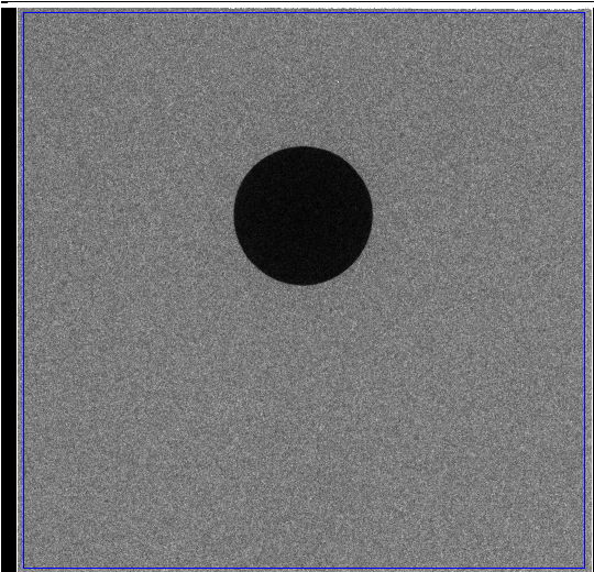
The figure below is a 5-second x-ray exposure of a KAF-0261 by an A2061C with a 2.5-mm tungston ball in front of the image sensor. This sensor provides 520 × 520 active pixels each 20 μm square, for a total image area of 10.4 mm × 10.4 mm.
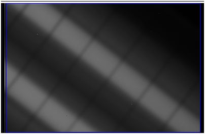
The dark current of the KAF-0261 is so low, we can expose to x-rays for several minutes. In this image we see the wires within a small thin-gap chamber (sTGC) along with some fiducial tungston balls, obtained over a 120-s exposure with 15-50 keV x-rays.
The A2061 complies with the LWDAQ Specification. The A2061A/B device type is 4 (KAF0400). The A2061C device type is 8 (KAF0261). Only four command bits are required to clear, expose, and read out the image sensor. These are VD2 and VD1, which operate the vertical clock phases of the image sensor, HD, which operates the horizontal clock phases, and DCEN, which enables 2 MPixel/s clocking of HD directly via the LWDAQ transmit logic signal.
| DC16 | DC15 | DC14 | DC13 | DC12 | DC11 | DC10 | DC9 | DC8 | DC7 | DC6 | DC5 | DC4 | DC3 | DC2 | DC1 |
|---|---|---|---|---|---|---|---|---|---|---|---|---|---|---|---|
| X | X | X | X | X | X | X | X | WAKE | LB | X | X | V2D | V1D | HD | DCEN |
The KAF-series image sensors require two vertical clock signals, φV1 and φV2, and two horizontal clock phases, φH1 and φH2, and one reset clock, φR. (For a detailed description and comparison of the KAF-series image sensor input voltages, see the A2063 Manual.) We are able to use the same vertical and horizontal clock phase voltages for all four sensors. But the φR must be modified to suit the KAF-0261. Thus the A2061C produces φR for the KAF-0261, but not for the KAF-0400, KAF-0401E, and KAF-0402. The change is accomplished by switching the values of R7, R40, and R38, as called for on the schematic.
To capture images from the KAF-0400, KAF-0401E, or KAF-0402, connect the A2061A to a KAF-0400 Sensor Head (A2063A or A2063B). If you are using a LWDAQ Driver (A2037E), you need firmware version 14 or higher. The LWDAQ Driver (A2037A) does not support these image sensors. All versions of the LWDAQ Driver (A2071E) firmware provide support. In the LWDAQ, select the Camera Instrument. Press the KAF-0400 button, which configures the Camera Instrument for KAF-0400 readout. There are similar buttons in the BCAM, Rasnik, and Dosimeter instruments, but you have to open the Info panel to see them. The Dosimeter Instrument always reads out a CCD image pixel-by-pixel from the image area, instead of transferring the image into a storage area line-by-line before reading it out pixel-by-pixel. The KAF-0400 has no storage area. The table below gives the Dosimeter Instrument parameters that use the KAF-0400 image area for radiation detection.
| Parameter | Value | Description |
|---|---|---|
| daq_device_type | 4 | Specifies KAF-0400 device LWDAQ hardware |
| daq_image_height | 520 | Number of rows |
| daq_image_width | 800 | Number of columns |
| daq_image_left | 20 | Left edge of active area |
| daq_image_top | 8 | Top edge of active area |
| daq_image_right | 784 | Right edge of active area |
| daq_image_bottom | 516 | Bottom edge of active area |
To capture images from the KAF-0261, connect the A2061C to a KAF-0261 Sensor Head (A2063C). If you are using a LWDAQ Driver with Ethernet Interface (A2037E), you need firmware version 17 or higher. The LWDAQ Driver with VME Interface (A2037A) does not support the KAF-0261. If you are using the newer and faster LWDAQ Driver with Ethernet Interface (A2071E), you will need firmware version 5 or higher.
| Parameter | Value | Description |
|---|---|---|
| daq_device_type | 4 | Specifies KAF-0400 device LWDAQ hardware |
| daq_image_height | 520 | Number of rows |
| daq_image_width | 520 | Number of columns |
| daq_image_left | 20 | Left edge of active area |
| daq_image_top | 8 | Top edge of active area |
| daq_image_right | 516 | Right edge of active area |
| daq_image_bottom | 516 | Bottom edge of active area |
The table above gives the Dosimeter Instrument parameters that use the KAF-0261 image area for radiation detection. You can configure the Camera, Dosimeter, BCAM, or Rasnik Instruments to capture with the KAF-0261 by pressing their KAF0261 buttons, which may be on the main panel or in the Info panel.
A206101B: The A206101B circuit board has one error that requires modification as shown below.
Resistor R50 must connect to OV, not U12-7. So we solder R50 off to one side and connect to 0V with a wire link.
A206101D: The A206101D layout has no errors. Both the A2063B and A2063C use this board, which fits in the PPL enclosure. The A2063C is identical to the A2063B except that resistors R7, R40, and R38 have different values, as show on the S2061_3 schematic.
Note: All our schematics and Gerber files are distributed under the GNU General Public License.