[15-APR-21] The Inplane Mask Head (A2052) is a Long-Wire Data Acquisition (LWDAQ) Device that drives nine IRLEDs (infra-red light-emitting diodes). The A2052A-8 has nine infra-red LEDs on the back side and three 8-mm snap-in standoffs. The A2052A-12 has 12-mm standoffs. The A2052A-0 has no snap-in standoffs.
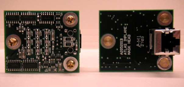
The A2052A has the same connector locations, LED locations, standoff locations, and board dimensions as NIKHEF's RASLED card. The RASLED is not a Long-Wire device. One functional difference between the two boards is that the RASLED card as a green LED that turns on when the LEDs turn on. The A2052A provides nine HSDL-4400 surface-mount LEDs on the top side and a straight-up RJ-45 connector on the back side. The diffuser and rasnik mask that the A2052A illuminates with its infrared LEDs are located precisely and permanently with respect to the structure whose deformations we are measuring with a rasnik instrument. The location of the LEDs themselves need not be precise. The standoffs has snap-fit ends that allow us to mount the A2052A by pressing its standoffs into three holes.
The A2052A replaces our prototype Inplane Mask Head (A2034).
The A2052 is complies with the LWDAQ Specification. It is LWDAQ Device type 1 (LED device) for the purpose of device-dependent jobs. The A2052 LED driver is element number 0 or 1.
| DC16 | DC15 | DC14 | DC13 | DC12 | DC11 | DC10 | DC9 | DC8 | DC7 | DC6 | DC5 | DC4 | DC3 | DC2 | DC1 |
|---|---|---|---|---|---|---|---|---|---|---|---|---|---|---|---|
| X | X | X | ON4 | ON3 | X | X | X | X | LB | X | X | X | X | X | ON |
Note that the A2052 ignores DC8, which is normally the WAKE bit for LWDAQ devices. But the A2052 has only two states: off or on. The off state is equivalent to the usual sleep state.
You will find the data acquisition steps required to capture an image and flash lasers on an A2052 in Rasnik.tcl, which is the TclTk script that defines the Rasnnik Instrument in our LWDAQ Software. In Driver.tcl you will find the routines that compose TCPIP messages to communicate with a LWDAQ Driver. We use these routines in Rasnik.tcl.
Connect the A2052 to a LWDAQ driver (such as the A2037) or multiplexer (such as the A2046) with a LWDAQ cable. You can use shielded or unshielded. Once you are capturing images of your LEDs, you can adjust the exposure time used by the flash_job to make them brighter or darker in the image.
Example: Suppose we want to illuminate nine LEDs in series. These nine LEDs are in an existing optical assembly. We have two wires coming out of the assembly, and the LEDs take 100 mA. The A2052A provides a two-way connector (P1) for the two wires, and will source 100 mA into them when the driver instructs it to do so. Pin one on the connector, which is uppermost in Figure 1, is the negative terminal of the LED current source, and pin two is the positive terminal.
We put a two-way socket on the two wires coming out of our instrument. We plug this into the A2052A. We connect the A2052A to a LWDAQ driver with a CAT-5 cable up to one hundred meters long. We note the device socket into which we plug the head, and determine the device address we should use with the driver to make it communicate with our device.
To flash the light emitting diodes, we tell the driver the address of the A2052A, and the type, which is one (1). We specify our desired on-time for the LEDs, and instruct the driver to execute a flash_job.
The A2052A flashes its bottom-side LEDs during a flash job. It comes with either 8-mm or 12-mm standoffs, and we can order other lengths as you require.
The A2052 is asleep whenever it is not driving its LEDs, so you never have to send it a sleep command. To measure the propagation delay of signals travelling from the driver to the A2052A and back again, you execute the loop_job and read the loop time out of the driver.
We intended the the A2052 to pass 80 mA through its nine LEDs. We miscalculated, and it passes 110 mA instead. The extra current, combined with the low forward voltage drop of the LEDs we used in our ATLAS circuits combined to make our A2052 vulnerable to damage when left on for more than a few hours. We describe this failure in the Reliability section of our Proximity Mask Head (A2045) Manual. When an A2052 suffers severe damage through over-heating, it's optical power output drops to 1% of its undamaged value. By replacing one of the 47-Ω power resistors (R3 and R4) with a 100-Ω resistor, we can stop the over-heating. As reported here, an A2052 with the 100-Ω resistor will remain on for at least a week with no damage.
To be sure of long LED life, we prefer the LED current to be around 80 mA. Some A2052s with one power resistor switched to 100 Ω still showed LED current of over 90 mA, so we switched both power resistors to 100 Ω in these boards, and so reduced the current to 80 mA. This contrasts with the A2045s made in a different year with a different batch of LEDs. In many of the A2045s, the current with a single 100 Ω resistor is only 70 mA.
The A2052 uses the same differential transceiver, clamping diodes, power supply switches, regulator, and logic chips as the Proximity Camera Head (A2047). For a discussion of the radiation tolerance of these components, see here. The LEDs on the A2045 are vulnerable to neutron radiation, as we describe in Pre-Production Radiation Tests.
We picked an A2052A at random and measured its power consumption in two states.
| State | +15 V | -15 V | +5 V |
| Off | 0.3 mA | 0.3 mA | 0.7 mA |
| On | 110 mA | 110 mA | 1.0 mA |
We intended the A2052A to pass 80 mA through its LEDs, but we miscalculated, as we describe above.
You will find the A2052 circuit diagram here, and printed circuit board files here.
Here is the A2052 circuit diagram.
Receiver and LED DriverHere are the two available printed circuit board layouts.
A205201B for A2052A.