The Quad Laser Head (A2050) is a Long-Wire Data Acquisition (LWDAQ) Device that provides four laser diode light sources.
| Version | Description | Origin |
|---|---|---|
| A2050B | Lasers mount on one side of PCB. | Brandeis University |
| A2050C | Lasers mount on two sides of PCB. Ten-way flex connector instead of RJ-45 socket. | Open Source Instruments |
| A2050D | Lasers on auxilliary board. | Weizemann Institute |
| A2050E | Lasers on auxilliary board. | Weizemann Institute |
| A2050G | Laser Drivers Replaced with Connectors. | Brandeis University |
The A2050B we designed to illustrate the circuit, but with no particular use in mind. Nevertheless, here it is, in use flashing four laser diodes in a test stand.

The lasers can be placed at a distance from the A2050 circuit board, but you should be sure to use leads no longer than 30 cm, and make sure the leads are soldered to the laser at one end, and soldered to the A2050B at the other end. If you use a connector, the lasers will be exposed to static electricity when they are disconnected.

The A2050C omits the RJ-45 socket, and replaces it with a ten-way flex socket. You connect the A2050C to another adaptor board that connects a ten-way flex socket to an RJ-45 socket. By this means, the laser board is mechanically isolated from the RJ-45 socket and the LWDAQ cable. The A2050C and its adaptor board were specified by Institut de Physique Nucleaire, France. They provided us with these front and side concept drawings.

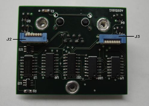
The A2051G omits the laser drivers on page two of the schematic (S2050_2) and replaces them with two six-way flex connectors, as shown in S2050_2a. The six-way connectors allow us to connect the A2050G to two A2049-compatible dual laser drivers.

The A2050G's flex connectors are one-sided, six-way, through-hole, straight-up, zero insertion force (ZIF) connectors, Digi-Key part number WM5301. By one-sided, we mean they provide electrical contacts on only one side of a flex cable. If the connectors at the other end of the flex cables are also one-sided, they must be oriented correctly, or else the cable will not connect the two circuits.
.
We designed the A2050G to work with one A2049F and one A2049G, as shown in the figure above. For board dimensions and hole locations on the A2050G, A2049F and A2049G, see this drawing. The CSC Rear Laser Pair (A2049F) connects to J2 on the A2050G, and provides source elements 1 (LD1) and 2 (LD2). The CSC Front Laser Pair (A2049G) connects to J3 on the A2050G, and provides source elements 3 (LD1) and 4 (LD2).
The A2050D has a number of problems in its original form, as we describe here. Unless you are sure these problems have been overcome by proper modifications, we recommend you do not use the A2050D in a large LWDAQ system. The A2050E is the Weizemann Institute's modified version of the A2050D. Look here to see how the two boards differ.
The A2050 is complies with the LWDAQ Specification. It is LWDAQ Device type 1 for device-dependent jobs, in particular the flash job. Device elements numbers 1 through 4 select lasers LD1 through LD4 for flash_job.
| DC16 | DC15 | DC14 | DC13 | DC12 | DC11 | DC10 | DC9 | DC8 | DC7 | DC6 | DC5 | DC4 | DC3 | DC2 | DC1 |
|---|---|---|---|---|---|---|---|---|---|---|---|---|---|---|---|
| X | X | X | X | X | X | X | X | WAKE | LB | X | X | ON4 | ON3 | ON2 | ON1 |
Use the A2050 with the BCAM Instrument. You will find the data acquisition steps required to flash lasers on an A2050 in the BCAM.tcl, which is the TclTk script that defines the BCAM Instrument in our LWDAQ Software. In Driver.tcl you will find the routines that compose TCPIP messages to communicate with a LWDAQ Driver. We use these routines in BCAM.tcl. So far as data acquisition code is concerned, an A2050 is identical to an A2051, except that the device_type is 1 for an A2050 instead of 2 for an A2051.
The A2050 obeys the LWDAQ power limits.
| State | +15 V | -15 V | +5 V |
|---|---|---|---|
| Asleep | 2.6 mA | 2.2 mA | 0.0 mA |
| One Laser On | 73.0 mA | 2.2 mA | 0.0 mA |
Here are the two pages of the A2065 circuit diagram.
Page 1: LWDAQ Receiver. Earlier versions of the schematic specified SN65LVDM180D for U1 and 10 kΩ for R2-R5. The SN65LVDS180D draws less current and is less expensive. We use 33 kΩ in the newer schematic, to reduce current consumption slightly, and eliminate 10 kΩ resistors from the circuit.
Page 2: Laser Drivers. Earlier versions of the schematic specified 10 kΩ for R16, R23, R30, and R37. But we now specify 33 kΩ for these four resistors, which set the monitor photodiode current more reliably for the LDP65001E laser.
Page 2a: Laser Driver Connectors. This is page two for the A2050G, which allows the A2050G to work with A2049-compatible dual laser drivers.
Here are the available printed circuit boards.
A205001B for A2050B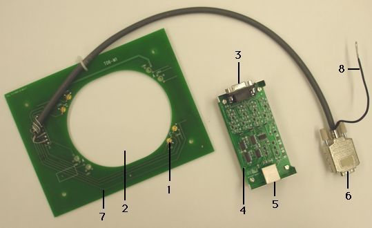