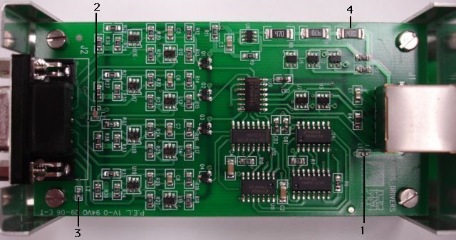
Figure: Close-Up of A2050D Circuit. Marked are (1) L1 connecting J1 shield to 0-V, (2) L3 in the power supply line for J2, (3) L2 connecting shield of J2 to ground, (4) additional power dissipation resistor.
The A2050D connects its RJ-45 cable shield to its 0-V power. The shield is likely, although not certain, to make contact with the A2050D chassis. In the assembly photographed above, the two were in contact. Because the chassis is connected to the local 0-V power, the A2050D introduces a ground loop into our LWDAQ system. The loop begins at the LWDAQ driver, passes along the 0-V power wire in the cable to the device, through L1, through the body of the connector shield, and so to the chassis, then to the chassis mounting structure, and so into the metal frame that supports the trigger chambers, through the frame to another A2050D, into its chassis, through its connector shield, through its own L1, onto its 0-V supply, and back all the way to the driver again along its 0-V power wire. This loop could have a cross-sectional area of tens of square meters, and end up carrying a hundred milliamps of 50-Hz alternating current, leading to several volts of 50-Hz mains hum throughout the data acquisition system.
Not only does L1 destroy the low-frequency star-grounding architecture of the LWDAQ, it also combines with C1 to compromise the high-frequency local-grounding architecture. We don't know the value of L1, but at some frequency it will combine with C1 to make a resonant tank circuit with high impedance, allowing high-frequency noise to induce voltage in the shield. Although less serious than the introduction of ground loops, the resonance of L1 and C1 will make the A2050D more sensitive to noise of a particular frequency. If this sensitivity causes the circuit to malfunction, we will have a hard time isolating the noise as the cause of our problems.
In addition to L1, there is also L2, which connects the J2 shield to the local 0-V supply. This shield is connected to a local chassis, we assume, by means of the J2 grounding wire (see photo). These parts guarantee that the A2050D will create a ground loop, because they connect the shield of both connectors to the local 0-V supply and to a local structure ground.
Vulnerable Lasers
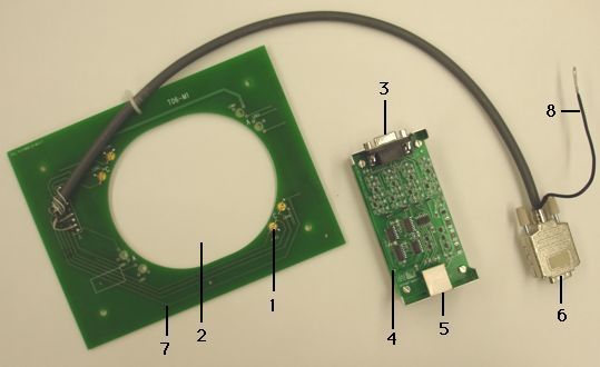
Laser diodes are vulnerable to static electricity. The A2050D separates the laser diodes from the circuit board, and inserts a connector between the circuit board and the lasers. The lasers are unprotected against static electricity, and therefore vulnerable. On a dry day, it will be easy to destroy a laser by touching one of its bare leads, or one of the pins on the 9-pin D-type plug.
Laser diodes are vulnerable to over-heating when driven with more than their recommended operating currents. In addition to the 30-cm cable and 10-cm PCB tracks that lie between the lasers and their driver circuits, there is also a new component, marked L3, in series with the +6-V connection to the laser mounting board. So far as we can tell, L3 is a low-pass filter made out of two inductors and a capacitor to ground. When the lasers turn on, this inductor will tend to push up the power supply on the laser mounting board beyond +6 V on turn-on, and so destabilize the driver control loop, driving the laser current above its designed value. In the long run, this will damage lasers that are already running at close to their 5-mW maximum power.
Limited Capacity
The A2050B uses two 47-Ω resistors in series with its 6-V regulator to dissipate some of the power lost when we step down from +15 V to +6 V. These are R6 and R7 in the schematic. The A2050D introduces a third 47-Ω resistor (see item 4 in photo). These resistors lie in series with the resistance of the +15-V and 0-V wires in the cable connecting the A2050D to its LWDAQ driver. If this cable is 100 m long, the resistance of each wires is roughly 10 Ω. When we add all these resistances together, we arrive at a total of roughly 160 Ω in series with the +15-V supply on its way to the +6-V regulator. The regulator itself uses a darlington transistor, and drops at least 1 V. The maximum voltage available for the resistors and the wires is 15 − 6 − 1 = 8 V. The maximum current the A2050D can supply to the lasers at +6 V is 50 mA.
A single laser and its driver can consume up to 70 mA, which is the maximum current the A2050B, with only two 47-Ω resistors, can supply to a laser at the end of a 100-m cable. Total cable length from driver to device in ATLAS has grown to almost 140 m. If the turn-on threshold current of a laser and its driver is 60 mA, it is possible that the A2050D will be able to turn it on at the end of a short cable, but not at the end of a long cable.
Noisy Power
The A2050 3.3-V logic power supply consists of a simple radiation-resistant regulator and a single 22-nF decoupling capacitor. Look for U7 and C3 in the schematic. The logic circuits have propagation delays of around 2 ns, and their outputs switch in less than 1 ns. We have learned from experience we must distribute 0-V to the logic chips with a solid copper plain, and 3.3-V with a lattice of thick tracks, or else our single decoupling capacitor is inadequate to keep the logic power supply stable.
The inductance of a 40-mm 20-mil track is of order 10 nH. With 1 V across this 10 nH, the current will increase at 100 mA/ns. The logic chips are switching up to 30-pF loads in 1 ns, so they draw 100 mA for 1 ns when they switch. With a 40-mm 20-mil power supply track, the power supply voltage at a chip will drop by roughly 1 V during the 1-ns transition. The chip's input thresholds will also drop in proportion to the power supply drop. We observed such dips in the power supplies on our earliest LWDAQ devices. The result was a circuit that worked sometimes, but not at other times.
The A2050D is a two-layer printed circuit board with no ground plane, and simple, isolated-track distribution of 3.3-V and 0-V power. Although the circuit may work some of the time, spikes on the power supply are likely to stop it from working at other times.
Conclusion
The A2050D breaks the LWDAQ cable shield grounding rules, and almost guarantees the introduction of large ground loops into the LWDAQ. Such loops are likely to stop the data acquisition system from working, and may damage it also, through excessive mains-frequency current and voltage in the 0-V lines. We recommend that no A2050D be connected to the ATLAS LWDAQ until both L1 and L2 have been removed.
The A2050D isolates its lasers from their drivers, making them vulnerable to static electricity. We recommend that the laser cables be screwed into the main A2050D circuit boards, and the screws be locked with glue, so that they cannot be removed easily. Locking the connector in place will protect the lasers on the laser mounting board.
The A2050D logic power supply is inadequately decoupled because it uses single tracks instead of a power plane or power grid. In our experience, inadequate decoupling of exactly this form makes the circuit unreliable. We recommend that 10-nF radial ceramic capacitors be soldered across the power supply pins of some or all of the logic chips, and that Weizmann Institute examine the power supplies during operation to make sure that they are stable.
It is possible, although unlikely, that A2050D lasers will work when the A2050D is on the end of a short cable, but not when it is on the end of a long cable. This is because of an extra voltage-drop resistor added to the circuit by the Weizmann Institute. We recommend that this resistor be removed, and replaced with a 0-Ω jumper, to restore the full current capacity of the laser drivers.
Update A
Lorne Levinson of the Weizemann Institute responded to our comments with a Word document. We are content with his proposed corrections to the A2050D. Our e-mail to Lorne is here.
Update B
We received a modified A2050D in a box on 31-AUG-06, together with two more laser mounting boards. We'll call this new version the A2050E. Neither laser mounting board was connected to the A2050E. We tested the A2050E and found it was always responsive to the LWDAQ, but the lasers connected to it were intermittent. We opened the box and found the following, modified version of the original A2050D.
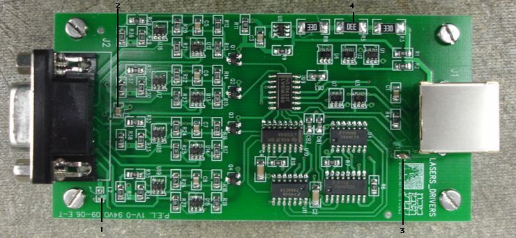
Figure: The A2050E. Compare to un-modified. The inductor at (1) has been removed. The inductor in the laser common power supply line (2) remains, but this will not affect the LWDAQ. The inductor at (3) appears to have been replaced by a capacitor. The 47 Ω resistors at (4) have been replaced by 33 Ω resistors.
We also note, from examining the new board, that Weizemann has added decoupling capacitors next to the logic chips. We believe their power supply decoupling is now adequate.
A close-up of R5 shows a faulty solder joint on one of the power dissipation resistors.
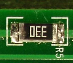
Figure: Faulty Joint on R5 on A2050E. This is a close-up taken from the previous image. The left side of the resistor is not soldered properly.
The remaining two 33-Ω resistors were poorly soldered as well. We re-soldered all of them, and the illumination of the lasers connected to the A2050E was no longer intermittent.
We have five laser mounting boards. The laser mounting board is part (7) in this picture. We tested all five with our repaired A2050E.
| Board | Performance |
|---|---|
| 1, Not Working from CERN JUN-06 | Three bright lasers, one dim |
| 2, Not Working from CERN JUN-06 | Three bright lasers, one off |
| 3, From CERN JUN-06 | Four bright lasers |
| 4, From CERN AUG-06 | Four bright lasers |
| 5, From CERN AUG-06 | Four bright lasers |
As we said above, the lasers on these mounting boards are vulnerable to static electricity. We can't say for sure if the two broken lasers were destroyed by static electricity, but it is possible. We assume that Weizemann tested all mounting boards before they sent them to CERN, so the damage must have taken place after shipping.
We tested our existing A2050D, and our new A2050E with an 80-m root cable. We used the Diagnostic Instrument to switch on and off the device power, to put the device to sleep, and to turn on the lasers by writing $FFFF to the device register. The A2050D turned on its lasers every time we turned on the device power, meaning that its power-up reset was failing, and the laser control bits were being set on power up. The A2050E, however, never turned on its lasers on power-up.
We reach the following conclusions.
- The A2050D does not power-up correctly, but the A2050E does power-up correctly.
- The A2050E is safe to connect to the LWDAQ, and should respond reliably to the LWDAQ.
- All laser mounting boards be screwed to their A2050E and never disconnected.
- All A2050Es be opened and their 33-Ω resistors be inspected for poor solder joints.