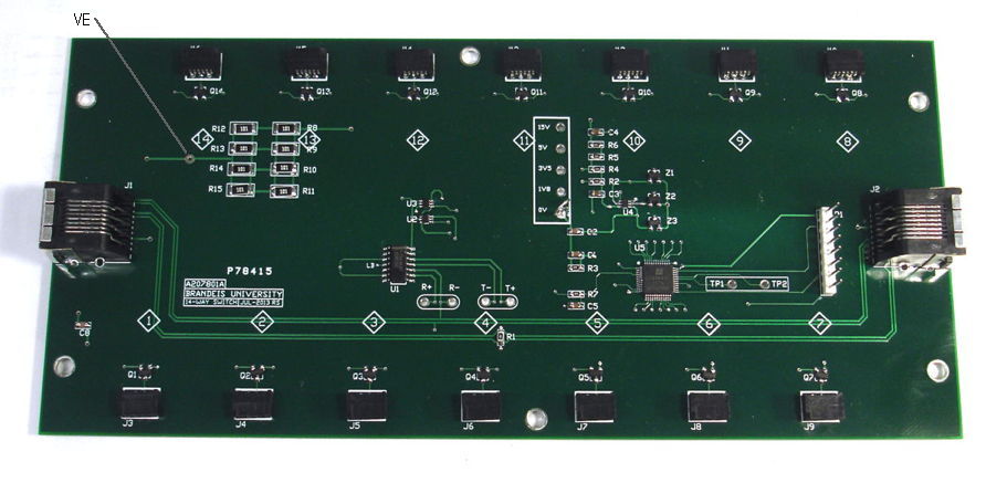
The Fourteen-Way Switch (A2078) is a LWDAQ device that provides fourteen power switches, each of which is available to auxilliary circuits through a six-way flex socket. The switches connect the auxilliary circuits to a 15-V power supply with fixed source resistance. In the case of the A2078A, this source resistance is 75 Ω with the capacity to dissipate 6 W. The A2078 provides two LWDAQ device sockets so that its LWDAQ connection can be made on either side.

The switch connectors are 1-mm pitch 6-way flex sockets, such as the . The connectors have contacts on only one side, the side farthest from the board edge. Pin 3 receives +15 V through 50 Ω. Pin 4 receives 0 V through a mosfet switch. When the switch is off, the auxilliary board is off. When the switch is on, the auxilliary board receives power. This pinout is compatible with auxilliary boards such as the Light-Emitting Diode Head (A2079A) and the Single Laser Head (A2074B). The pinout is also compatible with the Azimuthal BCAM Side Head (A2049) and Dual Laser Head (A2074), but only the first of two lasers in such circuits will receive power for its drive circuit when switched by the A2078.

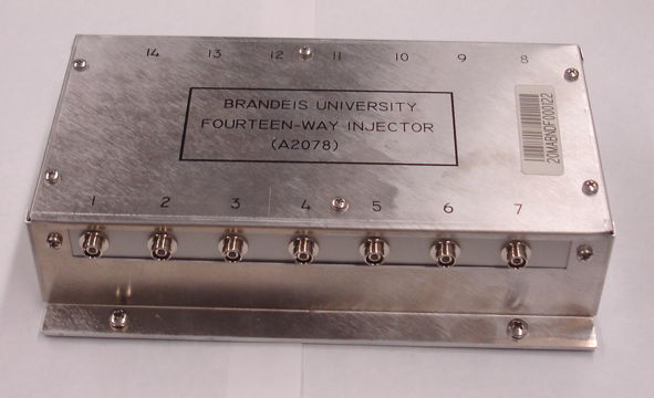
The Fourteen-Way Contact Injector, shown below, is a combination of a Fourteen Way Switch (A2078A) with fourteen Light-Emitting Diode Heads (A2079A). The fourteen auxilliary circuits are connected to the A2078A with two-inch flex cables.
The following table lists the existing versions of the A2078.
| Version | Description |
|---|---|
| A | Fourteen-Way Switch with 75-Ω 6 W Source Resistance |
The A2078A we designed for use in the Fourteen-Way Injector, which provides fourteen LEDs coupled to optical fibers. These Fourteen-Way Injectors provide blue light for the fiber-optic light sources in the BEE chamber alignment of the end-cap transition region in the ATLAS detector.
The A2078 is a LWDAQ device of type LED (1). It obtains power for its internal logic from the LWDAQ. The LWDAQ command bits are assigned as follows.
| DC16 | DC15 | DC14 | DC13 | DC12 | DC11 | DC10 | DC9 | DC8 | DC7 | DC6 | DC5 | DC4 | DC3 | DC2 | DC1 |
|---|---|---|---|---|---|---|---|---|---|---|---|---|---|---|---|
| ON14 | ON13 | ON12 | ON11 | ON10 | ON9 | ON8 | ON7 | WAKE | LB | ON6 | ON5 | ON4 | ON3 | ON2 | ON1 |
We turn on the A2078 power switches by sending LWDAQ commands to the device. Whenever we turn on a light source, we set two bits in the command word: the WAKE bit and the bit that corresponds to the light source. We can turn on a source using the Diagnostic Instrument by transmitting a hexadecimal command such as 0081 (turn on element one), 0082 (element 2), 0004 (element 3), 0088 (element 4), 008F (elements 1 through 4), and so on. In practice, we flash the lasers using a LWDAQ Driver flash job. In the BCAM Instrument, for example, set daq_source_device_type to 1 and daq_source_device_element to 1 through 14 to select one of the switches to turn on during the flash job. We assume the switch turns on a laser or an LED in the field of view of the BCAM.
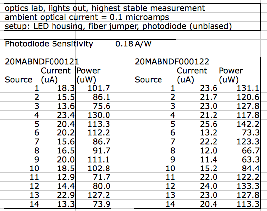
The following table gives the 460-nm optical power we measured at the fourteen outputs of two A2078As. The contact injectors use an EZ500C460 LED mounted in a QFN-8 package with no encapsulation. We press a zirconia ferrule against the LED surface, or within a few hundred microns of the LED surface, and transport the light to the FC union on the A2078A enclosure. We connect another fiber jumper to this FC union, and so present the light to our photodiode.

The output power varies from around 60 μW to 150 μW. Our target was 100 μW. These particular LED Heads (A2079A) presented us with problems because they have two vias on the circuit board that are shorted by the pad on the bottom of the QFN-8 package. Furthermore, the LEDs themselves are not always parallel to the package base. The result is that our ferrule, when pushed into the injector fixture, can go too far and break the cathode bond wire on the LED top side. The LED are not centered well either, and we know from measurements that the intensity of light on its surface varies by a factor of two from bright center to the edges. We are hopeful that we can guarantee 100 μW in the future. In the meantime, we are not certain that 60 μW will be too little power.
Note: All our schematics and Gerber files are distributed under the GNU General Public License.
S2078_1: Schematic, Logic and Power