 TCPIP-VME Interface (A2064) Manual
© 2005, Mike Bradshaw, Brandeis University.© 2008-2018, Kevan Hashemi, Brandeis University.
Distributed under the GNU General Public License
| Firmware | Software | Schematic | PCB | |
| Assembly |
The A2064 resides in standard VME crates and implements a LWDAQ Relay. Together with VME-resident LWDAQ Drivers such as the A2037A, the A2064 acts as a LWDAQ Server.

The A2064X/A/F fit in a standard 6U VME, 32-bit VME crate. In the figure below we have an A2064F providing TCPIP access to an A2071A VME-resident LWDAQ Driver.
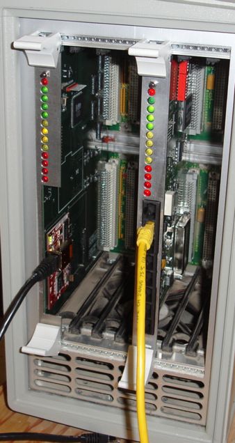
The A2064 always acts as a VME master. It translates commands it receives in LWDAQ TCPIP Messages into VME backplane read and write operations that control VME-resident LWDAQ Drivers. The A2064 is a VME 6U card with two 96-pin DIN plugs on the back side. It can select slaves with either 24-bit or 32-bit addresses.
The following table gives the existing versions of the A2064.
| Version | Description |
|---|---|
| A2064X | A206401B PCB, RCM2200 relay, socket at board center, 160 kBytes/s. |
| A2064A | A206401C PCB, RCM2210 relay, socket at board edge, 160 kBytes/s |
| A2064F | A206401C PCB, RCM3200 relay, socket at board edge, 360 kBytes/s |
The A2064's LWDAQ Relay is an RCM2200, RCM2210, or RCM3200. The relay communicates with a VME Interface via a 6-bit control address and an 8-bit data bus. The heart of the VME Interface is a programmable logic chip. You will find the logic programs for all versions of the A2064 here. The programs are in the ABLE language. The P2064A code is for the A2064X and A2064A.
You will find the steps required to connect to an A2064 and communicate with one of its LWDAQ Drivers in Driver.tcl, a Tcl script that defines routines like LWDAQ_set_base_addr_hex.
VME-resident LWDAQ Drivers each have a base address, which is the location of the first byte they occupy in the VME address space. The LWDAQ Driver with VME Interface (A2037A), for example, provides thirteen switches that set the top thirteen bits of its 32-bit base address. The VME Interface on the A2064 contains four eight-bit registers that specify the 32-bit base address of the VME Driver with which it will communicate. These base address registers reside in control address space, as specified in the following table.
| Base Address Register | Address Location | Description |
|---|---|---|
| DBA3 | 42 | Base Address, most significant byte |
| DBA2 | 43 | Base Address |
| DBA1 | 44 | Base Address |
| DBA0 | 45 | Base Address, least significant byte |
| VAM0 | 46 | VME Address Modifier |
The A2064's VME Interface overlaps the controller address space of the driver with which it communicates. Whenver the A2064's LWDAQ Relay writes to the control addresses 42 to 46, these writes are directed to the A2064's VME Interface. When the base address is zero, the LWDAQ Relay reads and writes from locations in the VME Interface's own address space. Because the control address is only six bits long, only 64 registers are available in the VME Interface. When the base address is non-zero, the VME Interface adds the control address to the base address to create the VME address it will use for a read or write cycle over the VME backplane. When the A2064 adds the base address and the control address, it assumes that the bottom 6 bits of the base address are zero. It uses the 6 control address bits to generate the lower 6 bits of the VME address.
By default, the A2064 executes 24-bit supervisory read and write cycles on the VME backplane. The VME Address Modifer it asserts on the backplane is 0x3D. But we can change the address modifier the A2064 asserts on the backplane by writing a new modifier value to the VAM0 byte at location 46.
The A2064 performs only eight-bit data reads and writes. Communication over the VME backplane would be faster with sixteen or thirty-two bit reads and writes, but the A2064's performance is limited by its TCPIP connection, not by the VME backplane. Even with single-byte reads, the backplane provides 2 MByte/s. The TCPIP data rate, meanwhile, is only 360 kBytes/s in the A2064F and 160 kBytes/s in the A2064X and A2064A.
All instrument panels in the LWDAQ Software allow the user to set the A2064 base address with a hexadecimal string by means of the daq_driver_socket parameter. To select driver socket 1 on the driver with base address 0x00E00000, set daq_driver_socket to "00E00000:1".
The A2064F programmed with firmware version 3 whould insert duplicated bytes into the data read from an A2037A. The freqeuncy of this duplication varied from one in a thousand bytes to one in a million bytes or less, depending upon the proximity of the A2064F and A2037A in the VME crate, and the values of the bytes themselves.
So far as we can tell, the byte-insertion problem occurs only with firmware version 3 on the A2064F. The problem is not caused by the ABEL source code for firmwaver verion 3, but rather the manner in which we compiled this source code. The A2064A/F uses the LC4256V-T176 programmable logic chip, which supports 1.8V, 2.5V, and 3.3V logic inputs, even though it is powered off 3.3V itself. The latest version of the ABEL compiler from Lattice Semiconductor defaulted to 1.8V logic levels instead of 3.3V. Because of the layout of the printed circuit board, there is a large bounce on the CDS (control data strobe) signal from the RCM3200 to the logic chip. Depending upon the relative phases of the RCM3200, logic chip, and A2037A clocks, and also upon transitions in data lines that ran parallel to CDS, this bounce might cause an interruption of CDS during a read cycle. When we set the logic thresholds to 3.3V logig, the byte insertion stopped in all three boards that had previously exhibited the problem. We compiled firmware version 4 in this way, with all inputs and outputs operating with 3.3V levels, and all outputs set to SLOW slew rate to reduce noise.
Although the byte insertions are rare in practice, we can provoke them reliably in A2064Fs with firmware version 3 using this script, which you can run in the LWDAQ Toolmaker. Comments in the script tell you how it works. Copy and paste the contents of the script file into the toolmaker. Adjust the IP address and base address to match your combination of A2064F and A2037A. Press Excecute in the Toolmaker panel. Wait for buttons to appear in execution window. Press Acquire and then open the BCAM Instrument. The script causes a black image with a vertical line of white spots in the center to be written to the RAM on the A2037E. When you press Aquire, this image is read out of the A2037E and plotted in the BCAM Instrument. Open the BCAM Instrument to view the image. The script uses the Toolmaker execution window to display any changes that occur in the position of the top two spots in the row. If you see the vertical line of spots drifting, you know that byte-insertion is taking place.
Note: All our schematics and Gerber files are distributed under the GNU General Public License.
The A2064A and A2064F use the same logic chip and have almost identical connections to their RCM2200 and RCM3200 modules. There is, however, one difference between the two: the RCM data lines are in reverse order in the A2064F, so the firmware must be different. You will find the latest version of the ABLE source code here, with names "P2064xyy.able". Starting with version P2064F04.abl, there is no separate version of the code for the A2064A. Compiler directives allow the same source code to produce both jedec files. The jedec files, which are the product of compilation, are named "P2064xyy.jed".
The RCM2200 and RCM3200 modules of the A2064A and A2064F respectively use the same TCPIP messaging code as the A2037E. You will find the latest version of the C source code here, named "C2037Exx.c". When we compile the code, we set the PLATFORM constant to suit the RCM module, as we describe in the comments of the code. The compiled file name has the form "C2064xyy.bin". You will find the latest version of the RCM binary files here.
The schematic is poorly-scanned and hard to read. It does not appear to include the connections from the logic chip to the RCM3200 module on the A2064F. We will try to re-draw or re-scan it one day when we have time. Until then, apologies for ambiguity.
S2064_1 RCM2200 InterfaceNot available.