 Repeater (A2058) Manual
© 2004, Mike Bradshaw, Brandeis University.© 2006-2009, Kevan Hashemi, Brandeis University.
The Repeater (A2058) is a LWDAQ Repeater whose function is to re-transmit signals sent from the LWDAQ driver to a LWDAQ device and turn off the power to multiplexers and devices.
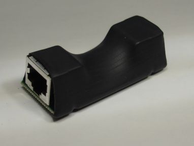
The A0258A connects directly to a driver socket with a root cable. Both connectors are shielded, and so appear identical from the outside. The only way to tell which connector should be used to connect to the driver is to look at the markings on the bottom of the enclosure.

The first root cable is the one that leads to the driver. The second root cable leads either to a multiplexer or an individual device. When the driver transmits device address zero down the first root cable, the repeater turns off power to the second root cable, thus turning off power to any multiplexer or device at the end of the second root cable.
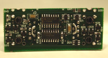
Inside the heat shrink, the A2058A looks like this:
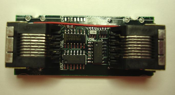
The A2058A provides a straight-through connection for the cable shield. The heat-shrink enclosure is non-conducting, making it impossible to provide a chassis ground connection, and such a connection should be avoided because it might introduce ground loops into the root cable shields.
With the help of the A2058A, the LWDAQ maximum root cable length can be increased from 150 m to over 200 m, as we show in the LWDAQ Cable Manual.
For details of how we turn on and off a repeater, look at the Analyzer.tcl script that comes with our LWDAQ Software. Turning off a repeater is the same as selecting channel zero on a multiplexer. You will find the steps required to switch from one multiplexer channel to another in Diagnostic.tcl, a Tcl script that defines procedures like LWDAQ_sleepall_Diagnostic. This procedure goes through all driver and multiplexer sockets of a LWDAQ system and sends all devices to sleep. It uses LWDAQ_set_driver_mux, which is defined in Driver.tcl. In Driver.tcl, you will see how to compose a TCPIP message for a LWDAQ Driver that will instruct the driver to select a particular multiplexer channel.
We picked an A2058 at random and measured its power consumption in two states.
| State | +15 V | -15 V | +5 V |
| Power Off | 0.35 mA | 0 mA | 7 mA |
| Power On | 0.35 mA | 0 mA | 7 mA |
Note: All our schematics and Gerber files are distributed under the GNU General Public License.
The A2058 circuit is very similar to that of the LWDAQ Multiplexer in that it uses the same LVD transceiver and address receiver. The A2058 uses an unused bit in the address word to turn on/off the +5V,+-15V voltage supplies to any device connected to it.
The A2058 functions as a command word repeater. It receives and retransmits command words sent from the driver to the device. It is important to note that the A2058 restores signal loss of the command word, but does not restore power loss due to transmission line length.
Here are the two pages of the A2058 circuit diagram:
Page 1: LVDS TransceiverPrinted circuit board files: A205801C