 BCAM Development
© 2020-2021, Kevan Hashemi, Brandeis University© 2022-2023, Kevan Hashemi, Open Source Instruments Inc.
Starting in September 2020, we record here our day-to-day work on BCAM cameras, sources, and electronics. Refer to the BCAM User Manual for a description of the BCAM.
[02-SEP-20] The source plates we made for the ATLAS New Small Wheel (nSW) hole the ferrules at the end of four optical fibers, with two facing one way and two the other. We have the plates made, insert 2.5-mm zirconia ferrules, measure the center-line of the ferrules with respect to the plate's BCAM-like kinematic mounting balls, intersect the center-line of each ferrule with a plane a set distance from the front or back face of the plate, and so obtain four points in mount coordinates that represent the centers of the polished ends of the fibers when we later install fiber-loaded ferrules in the source plates. The distance from the fiber tip to the face of the plate is not critical, because it is parallel to the axis of the viewing BCAM. The fiber ferrules we push all the way into their mounting hole and by construction the tip is within ±100 μm of the correct distance from the face.
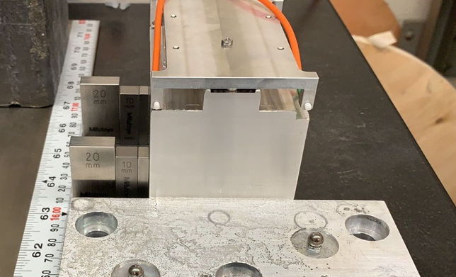
We made two types of source plate: wide and narrow. The wide plates have the sources on each face separated by 60 mm in the direction perpendicular to the fiber axis, while the narrow plates have their sources separated by 30 mm. We are installing roughly 2000 wide source plates and 200 narrow plates in the nSW.
We translate source plates across our granite beam, using the method we describe in BCAM Calibration on the Granite Beam, and so obtain a measurement of the separation of the two sources. We fasten the source plate to a kinematic mount and displace the mount perpendicular to the axis of a BCAM camera, at a range of one or two meters, with gauge blocks to set the displacements. We move 35-mm in 5-mm steps. We compare the separation we measure on the granite beam with that which we obtained with the CMM.
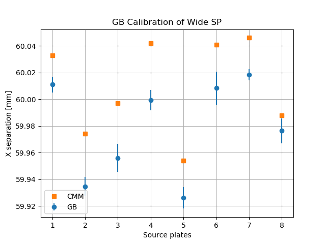
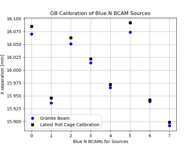
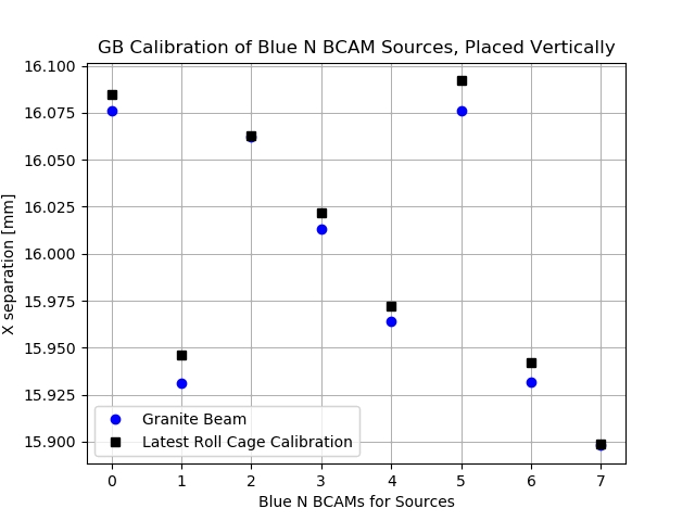
The granite beam measurement of separation is roughly 0.05% smaller than the CMM measurement. We repeat these measurements for BCAM sources, which are lasers mounted on the front face of a BCAM. We measure the separation of source on ten BCAMs, first with the sources separated in the horizontal direction while we translate them horizontally, then with the sources separated vertically while we again translate horizontally. Once again, the granite beam measurement is 0.05% smaller, and we are pleased to note that the vertical and horizontal measurements give the same result on the beam. Our calibration of magnification by horizontal displacement gives us ±0.01% accurate calibration in the vertical direction as well.
Meanwhile, we are constructing the alignment system of the nSW at CERN, and we look at the self-consistency of the instruments on a partially-constructed wheel. We have alignment bar measurements by the CMM at Freiburg, BCAM calibrations made at Brandeis and checked at CERN, and source plate measurements made at Brandeis. We take images of all sources with all cameras that view the sources, and run ARAMyS to reconstruct the bar positions and chamber positions. In ARAMyS Source Plate Calibration Study, we find that the optical location of the sources appears to be 0.7 mm inside the ferrule.
[07-OCT-20] We have a new Azimuthal BCAM adaptor plate, shown below, that brings the azimuthal BCAM pivot point to the axis of the roll cage.

We say the base plate is forward-facing when the arrow made by its kinematic mounting balls points towards the source block, which is to the right in the view above. We say it is backward-facing when this same arrow points away from the source block, as shown above. When we place the roll cage on the base plate, regardless of the orientation of the base plate, the kinematic mount closest to the source block is the front mount and the one farthest from the source block is the rear mount. The front and rear mounts share the two middle balls on the roll cage.

We have two source blocks for BCAM camera calibration. A large one with optical fiber sources on a 50-mm square, and a small one with laser diode sources on a 16-mm square. Both are shown below.
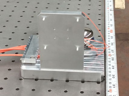
With the base plate in the backward direction, the plate on the forward mount, we can calibrate the Black Azimuthal BCAM, so long as we use the small source block. We calibrate Blue Azimuthal BCAMs with the base forward using the front mount.
[18-MAR-21] Our large source block has one flaw: it does not sit square to our calibration straight edge. The two balls that press against the straight edge are not equidistant from the edge of the block, and as a result the block is rotated by about 10 mrad.
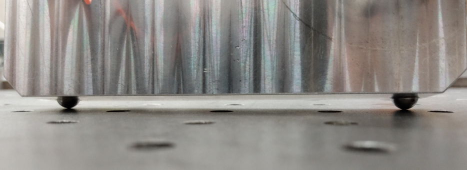
We shim the source block so that it is parallel to the straight edge and re-calibrate a BCAM camera. The pivot.z position moves back, away from the source block, by 0.15 mm, which is not significant, but is consistent with the sources being 0.15 mm closer to the BCAM during calibration. No other parameters change significantly. We move the source block 10 mm perpendicular to the straight edge in the near and far positions and calibrate the same camera again. We see no significant change in any calibration parameter.
[03-MAY-21] We place the source calibration reference camera so that it the two rear sources of a Black H-BCAM are on the extreme left of the image, and proceed to calibrate. We restore correct orientation of the reference camera and calibrate again.
Off-Center:   -4.585  35.174 -20.594  35.217 -80.610
On-Center:    -4.596  35.173 -20.583  35.217 -80.610
[13-APR-22] We have three H-BCAMs returned from FNL. To of them, R0213 and R0214, have all four lasers damaged. They were calibrated and shipped at 5 mW output, now emit 0-2 mW depending upon the laser. We see evidence of over-heating in Q1-Q4. The SOT-23 package is discolored. The solder is dull and crinkled on the surface. Resistors R7 and R14 are discolored or charred.
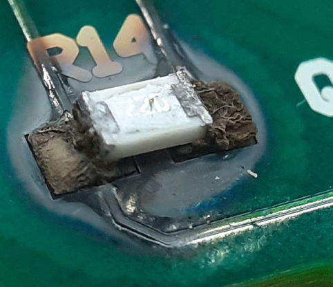
If the laser fails as a short circuit, the drive circuit will apply the maximum current it can through the laser. We could see up to 200 mA flowing through R7 or R14, dissipating 1 W, which will soon burn the P0805 resistor. We can think of only one explanation for these failures: the lasers were left on for several thousand hours.
[25-APR-22] At CERN, where we have hundreds of N-BCAMs and D-BCAMs installed at the end of 100-m cables with multiplexers and repeaters, we find that one multiplexer is plagued by bad BCAM images unless we send a wake-up command to the camera and source BCAMs before we start doing anything with the image sensor or flashing a laser. Our hypothesis is that the power supplies are taking longer to establish themselves than they should, and this is the result of a fault in the multiplexer or the root cable. In LWDAQ 10.4.1 we add a "wake" command to wake up both source and camera BCAMs before we begin to flash or clear. Now all the images are perfect. Our hypothesis is that the clear operation causes the ICX424 to latch up if the power supplies are not settled, and the flash fails to produce any light if the power supplies are not settled.
[25-MAY-22] We repair three H-BCAMs. We replace all eight lasers on two Black H-BCAM Side Heads (A3026L), as well as current limiting resistors R7 and R14 on each side head, and Q1..Q4. Laser output power now 3.5-5.0 mW. We replace one images sensor. We replace U11, the analog switch, on one H-BCAM Head (A3025A). We rebuild all three H-BCAMs. For a 500-ms ambient exposures, we see white spots in most image sensors, but not in the new image sensor. We speculate that some of the sensors have been exposed to fast neutrons.
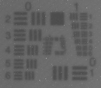

[18-OCT-23] We have ten new and two pre-existing Black H-BCAMs (BCAM-HL) with 1.5-m focal range and 5-mW lasers. We calibrate with roll cage at Tufts University. One has a blob of solder on the rim of the aperture in the laser board, which reflects the overhead light as a stripe on the image sensor. We cut off and remove the blob. One has a loose front plate, which we fasten before calibration. Two have dirt on image sensors that we manage to clean off with tissue and anti-static foam cleaner. All calibrate fully. For the two pre-existing, differences between earlier and today's calibrations are insignificant.


The pivot x and y coordinates are within ±100 μm, which is well within our 5-mil machining tolerance. The axis direction is within ±3 mrad, which corresponds to ±150 μm at the CCD. The pivot-ccd average is within 100 μm of nominal, and range is ±0.4 mm. The large standard deviation in pivot.z for the front cameras is due to C0610's value of −4 mm.
[03-NOV-23] In our geometry routines, mainly utils.pas and bcam.pas with Tcl interpreter interface in lwdaq.pas, we switch from defining a BCAM mount coordinate system with an origin and three axis vectors to defining mount coordinates with an orientation and location in global coordinates, which we call a "pose". We check that BCAM calibration constants are all identical before and after these changes. The new routines will be available in LWDAQ 10.6.4. Our purpose is to permit us to construct a large system of BCAMs and apply our simplex fitter to adjusting the pose of each BCAM mount so as to minimize the error in image positions. We now have generic local to global coordinate transformation routines that we can use with the pose of the local coordinate system. A bcam_coord_from_mount routine provides the pose of the mount from its ball positions.