In-Bar Component Assembly Nzotes
© 2009 Alex Asen, Brandeis University.
www.bndhep.net
Contents
Introduction
General
Rail
Labeling
End Cap
CCD Station
Lens Station
Mask Station
RTD
Wiring
Introduction
These are notes on the assembly of the In-Bar Alignment System. They may be useful to anyone repairing a bar at CERN or building a new bar. The notes were compiled after creating the EE bars. We tried to assemble EE bars in a manner consistent with earlier bars, but there are differences.
General
- It saves a lot of time to measure lenses first. We ordered f=510mm and got a range from f=506 to f=518.
- We had to work with a spread of lens focal lengths, so we created 9 different combinations of short and long focal lengths and M4 clearance hole coordinates to match each combination. See Labeling for further explanation.
- Some pieces are anodized, some are not. The only pieces that must be anodized are the collimators and the CCD plates. If other pieces are anodized it is because they were recycled from an earlier design.
- Dynasolve nicely separates epoxy from aluminum. It is not difficult to use, but Dynasolve is very strong stuff and after using it once, you will be eager to not make any more mistakes that require it.
Rail

Click on the image to enlarge.
- We used the rail to test every set before we shipped it.
- We loaded this script into the Acquisifier and tested the RTDs with the Thermometer Instrument.
- The mounting hardware is not perfectly centered on the sleds. It is off my up to 2mm. Do your best to test and fix this before using the rail. We used an Excel sheet to adjust the drawing's numbers to fit our imperfect sleds.
- We used a metal ruler along the front of the sled as a straight edge to measure the sled's position on the rail. If you have to measure off the back of a given sled because the front is blocked by a support bar from the wall, it is useful to know that each sled is 152.4mm long.
Labeling
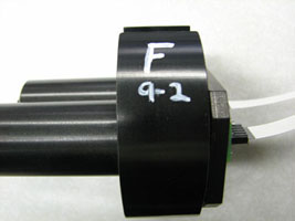

- Each station is labeled "A" - "F". While the pieces in most sets are interchangeable, this is the layout we tested on our rail and are most confident in.
- The first 12 sets all used similar lenses and the same drawing. We then had to start mixing and matching lenses and creating unique drawings. We created nine different combinations. The combinations are labeled "set #1" through "set #9". You can check that a set of components and a drawing match because the drawings includes a chart with "set #", the "focal length short" and the "focal length long". Each lens and mask station have a focal length written on them as well as a "set #"
- For example, the station in the picture above is labeled "F 9 - 2". The "9" refers to the "set #", and points you to the appropriate drawing. The "2" means this is the second type "set #9" and goes with other stations labeled "9 -2". The "F" refers to the stations position on the drawing.
End Cap
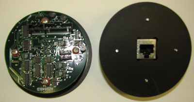
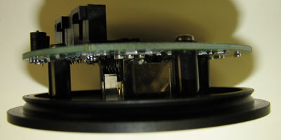
- An A2044 sits on top four .5" plastic stand-offs. Use nonconductive washers and stand-offs.
- Some older versions used screws with a pozi head. The pozi head is similar to philips and can be turned with a philips screw driver, but is difficult to grip without a pozi driver.
- We have a lot of spare end caps, but they are all slightly different from each other. The A2044 only fits in one direction, but it is tricky to figure the correct direction. Not all screws will go down at a 90 degree angle, but all should be close to 90 degrees. Also, some screw holes are stripped, so you may want to check first.
- Check that the edge of the circuit board does not prevent the cap from fitting inside the bar. If it does, the A2044 probably has to be rotated relative to the cap.
CCD Station
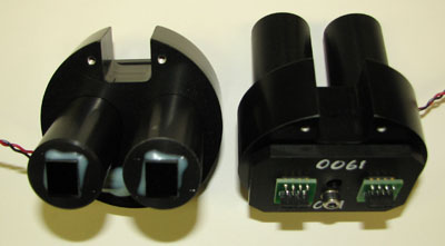
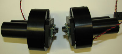
- The CCD plates sits on top a cone/slot/flat. When bolting it down, use just enough force to flatten the split washer -- this is much more force than you would normally use on a cone/slot/flat, but still less force than tightening it as hard as you can.
- Unlike the other stations, there are no strain relief holes for the RTD wire. Use a generous amount of epoxy to hold it down, but be sure to leave a 5mm buffer between the edge of the station and the edge of the epoxy so that the station can be screwed down to our testing rail. This is sometime difficult because the epoxy likes to slowly spread out as it dries. If you end up with too much epoxy it is pretty easy to file off.
Lens Station
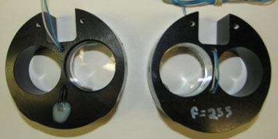
- A tiny amount of epoxy will hold the lens firmly.
Mask Station
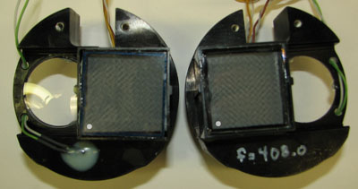
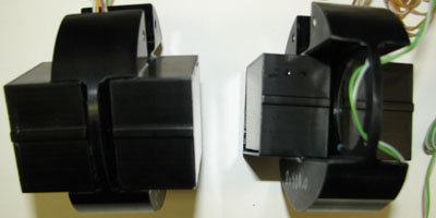
- All RASNIK mask are built with the dot in the mask's bottom right corner. So when looking at the mask, the dot is on the bottom left corner.
- For consistency the raised lip on the side of the mask is always closer to the top of the station than the bottom.
- The On-bar Mask Assembly Manual is a useful reference for making in-bar masks. Some things in the manual are not applicable to the in-bar masks, but there is nothing in the manual that should steer you in the wrong direction.
- We used some recycled front and back spacers with widths that varied a few millimeters from the drawings. Our tests showed that this did not change the readability of the RASNIK.
- The power wires are soldered directly to the A2041 board. Heat shrink is used to protect and isolate the joints. We soldered the wires from behind after the mask was assembled, but before it was glued into the mask station. Please see Wiring for more information.
- On most of the EE Mask Stations, early in production, we systematically miscalculated the focal length of the lens. The focal length written on the station is usually 2mm greater than the actual focal length. We later took this error into account when specifying the M4 clearance holes in the drawings, and then tested every set on our rail, so all images should be sharp. To avoid confusion, in the drawings we refer to stations by the focal length they are label with, not the actual focal length.
RTD
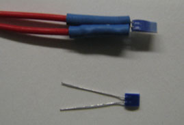
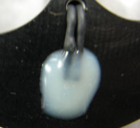
- We super-glued the RTDs down to the aluminum before covering them in epoxy. RTDs are made of a tricky material to super-glue. It is important to use a very small amount of glue and moisten the surfaces by breathing on them before applying the glue. Supper glue sets in moisture.
- Most RTDs came with a red wire pre-soldered to them. We then soldered and heat-shrank our color-coded wires to the red wire. Later in assembly we used acid flux to solder the RTDs directly to our color-coded wires.
Wiring
| A2044 - P1 |
| Pin |
Function |
Color |
Wire Length (CM)
|
| 1 |
CCD Station RTD (-) |
Red |
26 |
| 2 |
CCD Station RTD (+) |
Red (later black) |
26 |
| 3 |
Lens Station RTD (-) |
Blue |
80 |
| 4 |
Lens Station RTD (+) |
Blue-White |
80 |
| 5 |
Mask Station RTD (-) |
Green |
145 |
| 6 |
Mask Station RTD (+) |
Green-White |
145 |
| 7 |
Empty |
|
|
| 8 |
Empty |
|
|
| A2044 - P2 |
| Pin |
Function |
Color |
Wire Length (CM) |
| 1 |
LED Array Long (-) |
Brown |
143 |
| 2 |
LED Array Long (+) |
Brown-White |
143 |
| 3 |
LED Array Short (-) |
Yellow |
143 |
| 4 |
LED Array Short (+) |
Yellow -White |
143 |
