
Figure: Tapering Machine, 64cm long. Translation stages and torch (center), index motors (left and right), A2060C (upper left), index drive (top).
The tapering machine consists of two motorized translation stages and a stationary propane torch. The two translation stages hold either end of an optical fiber and translate it back and forth over the flame while applying tension. This process stretches the fiber, narrowing the diameter of the heated section. This process can be used to create tapers and narrow waist sections in optical fibers.
Each translation stage is an NRC model 430 with attached micrometer. A steel plate with a shallow groove is attached to each stage. An optical fiber is placed onto the groove and strong magnets are used to hold it firmly in place. To securely clamp the fiber onto both stages, it must be at least 75mm long. The groove extends the full length of the steel plate, so there is no maximum length to the fibers used.
The micrometer of each translation stage is attached to an M061-CE02 stepping motor, made by Superior Electric. Each motor is controlled by a 440-EPI10 Indexer Motor Drive. These indexer drives are programmed by computer via the A2060C RS232 Interface. They are connected in a "daisy chain" configuration as described in their opration manual, allowing commands to be sent to both devices from a single A2060C.
There are two limit switches attached on the frame near each stage. The limit switches are wired to the indexer drives and prevent each motor from pushing the stage past its mechanical limits. There is an additional limit switch mounted on the right stage that prevents the motors from pushing the two stages against each other. The limit switches are hardwired to the indexer drives in such a way that they do not require additional programming for motion to stop when activated. See section 5.1 of the indexer drives manual, "Parallel Port Data Assignments" for more information on wiring limit switches.
A metal fixture holds a torch nozzle which points a blue 12mm long flame at the optical fiber between the two stages. A standard 400g propane cylinder (commonly available at U.S. hardware stores) provides the fuel. A main valve is attached to the cylinder which allows the propane to be shut off between uses. Close to the main valve is a brass valve that provides precise control over the fuel flow rate. It is used to control the size and shape of the flame. Propane flows through about one meter of 7mm plastic tubing to a ball valve. This ball valve allows the flame to be quickly switched on and off during use. A piezoelectric sparker is used to ignite the flame.
The indexer drives are connected in "daisy chain" configuration as described in their operation manual. This allows a single RS232 connection to the drives to control each indepentently. One drive has been programmed with the identity "01" and the other with "02"; they are labeled appropriately. The drive to be operated is identified in the RS232 command which is sent to both drives.
To send RS232 commands, we use an A2060C, which is operated by the Terminal instrument. Commands to the index drive can be typed directly into Terminal. The command to be sent should be entered into the tx_ascii field. The indexer drives require that every command be terminated with a carriage return, line feed (CRLF). This should be omitted from the tx_ascii field and included in the tx_footer field by setting it to "13 10". Other recommended configuration parameters for Terminal are shown in the table below.
It is possible to set parameters such as motor speed as well as to send commands that start or stop motion. For example, the ascii command "<02 H4 H3" (terminated, as always, with a CRLF) commands index driver number two to prepare for high speed motion in jog mode (in which the motor turns when instructed until another command is received). Subsequently sending the ascii command "<02 H6" commands motor number two to rotate clockwise in high speed jog mode.
It is also possible to pre-load and execute a program via RS232 which defines a complex set of motion. Each line is programmed individually. For example, sending the line "<01 N1 X+2000 F1000" CRLF and "<01 N2 X-3000 F500" CRLF creates a simple program that, when exectued, will move motor number 1 2000 pulses at 1000 pulses per second in the clockwise direction followed by 3000 pulses at 500 pulses per second in the counterclockwise direction. A full list of RS232 commands can be found in section 6 of the indexer drive manual.
With the drive's L70 parameter set to 1/10 step mode, 4,000 pulses correlates to two revolutions of the motor and 1mm of motion of the stage.
| Parameter | Value |
| analysis_enable | 0 |
| rx_last | 0 |
| rx_size | 1000 |
| rx_timeout_ms | 1000 |
| tx_file_name | |
| tx_footer | 13 10 |
| tx_header | 19 |
Taper is a LWDAQ tool that automates control of the tapering machine to produce optic fiber tapers. It is designed to produce biconical tapers which may have a waist section of constant diameter. It was designed with the assumption that the fiber would be trimmed near its waist section with the left taper being kept and the right discarded. Therefore, the biconical taper may be slightly assymetrical.
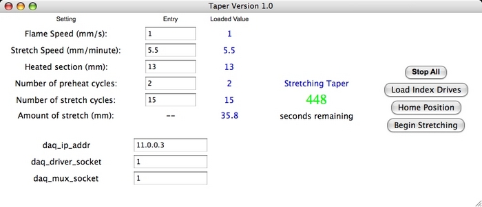
The stretching algorith begins by translating the fiber over the heat source to burn off the fiber's polyimide coating. Both stages move with the same velocity, defined by Flame Speed. After translating a distance defined by Heated Section, the stages reverse direction. The complete back and forth translation is one cycle. The stages will complete as many cycles as is defined by number of preheat cycles. The stages then continue translating back and forth except that the leading stage moves at greater speed than the following stage. The difference in speed is specified by Stretch Speed. The following stage moves the distance defined by Heated Section while the leading stage moves slightly further. After completing motion in one direction, they simultaneously reverse direction. A complete back and forth motion is one cycle, and the number of cycles completed is specified by Number of Stretch Cycles. After completing the final stretch cycle, the stages perform a half cycle that continues for an additional three seconds. This moves the working part of the taper away from the flame so that it is not disturbed when the fiber halts.
After opening Taper and setting the address of the tapering machine, click "Home Position". Each stage will retreat to its mechanical limit away from the machine's center. They will then index off of the limit switches a pre-programmed distance. When each drive comes to a full rest, the home position has been reached. The fiber can now be placed into the groove and locked magnetically into place. Next, the drives must be programmed to create the desired taper profile. Enter the tapering configuration parameters Stretch Speed, Flame Speed, etc. Upon clicking "Load index drives", the tool will create a program according to the motion algorithm described above based on the entered parameters. It then loads this program to the index drives. Pre-loading the program to the drives rather than issuing new commands as the fiber is being stretched eliminates network speed consistency as a source of error. The message "Program Loaded" will appear when this process is complete. At this point, the flame should be turned on and adjusted until the inner blue cone is touching the fiber. Clicking "Begin Stretching" commands the drives to initiate the program that was just loaded. The tapering machine will conduct the motion described above. A countdown timer appears on the screen which indicates time to completion. When the motion is finished, the flame can be turned off. To remove the taper from the machine without damaging it, first unclamp the right side. Clip the fiber near its waist using diagonal cutters and discard the right taper. The left taper can then be unclampled and safely removed. If the machine must be stopped at any point, the "Stop All" button should be pressed to stop the motors.
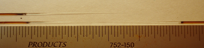
The tapering machine is designed to taper fibers from 300 to 600 microns in diameter, though other fibers may be usable. To produce a taper of arbitrary size and shape requires experimenting with the configuration parameters. For nearly all applications, two pre-heat cycles should be used. This is generally sufficient to cleanly remove all polyimide. Generally, faster stretch speeds produce more steeply angled tapers. We generally adjust Stretch Speed for primary control of the taper angle, Heated Section for the taper length, and Number of Stretch Cycles for the final diameter. This is only a guiding principle; the parameters must be adjusted in concert to obtain an arbitrary taper shape. The range of acceptable values is goverened by the physical size of the system. Using the Taper tool, the greatest biconical taper length possible is about 50mm.
| Parameter | Suggested Value |
| Flame Speed (mm/s) | 1 |
| Stretch Speed (mm/min) | 3 - 10 |
| Heated Section (mm) | 5-15 |
| Number of preheat cycles | 2 |
| Number of stretch cycles | 2-20 |