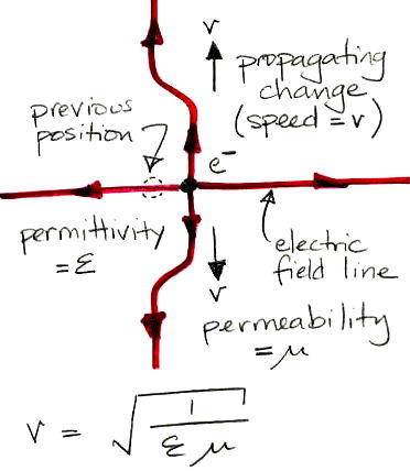
Figure: Propagating Disturbance in an Electric Field. The electron recently moved to the right.
| Brandeis University | Physics 29a |
| Spring 2020 | Kevan Hashemi |
Imagine an electron sitting alone in a vacuum, and an electric field sensor at a point some distance from the electron. The electric field we measure decreases as the inverse of range. The total energy of the field around the electron is infinite. If we move the electron a short distance, its infinite field must change. But the field cannot change immediately at all ranges. Maxwell's field equations dictate that changes in the electric field propagate outwards at a speed equal to the inverse square root of the product of the permeability and permittivity of a vacuum, which is the speed of light.

Electric field lines cannot end in mid-space unless there is a charge present for them to end on. We say the divergence of the electric field is zero when no charge is present. When we move the electron, we know the field lines must move over, but there is a place where the old and new field lines must meet. In this place, the field lines cannot stop in one place and start in another. The new field line must turn and cross over to the old field line, producing a kink in the electric field.
When we look at Maxwells equations, we find that must exert a force upon the electron to move it. The work we do when we move the electron goes into forcing the field around the electron to change, and this change propagates outwards to infinity, causing the entire field to conform to the electron's new position. At any point in time, the energy we put into moving the electron exists at the propagating kink in the electric and magnetic field lines. In a vacuum, this kink propagates at three hundred million meters per second.
Imagine a second electron in the path of the propagating kink. As the kink passes over the electron, the electron experiences a force to the left. We move the first electron to the right, and the second electron experiences a force to the left some time later. The magnitude of the force is proportional to the local field strength, which we have already concluded to be proportional to the inverse of the range. The time delay between the movement of the original electron and the occurrence of the force on the second electron is equal to the range divided by the speed of light.
Aside: How can we say that it is the first electron that moved and not the second one? Surely we could pick a frame of reference on the first electron, and consider the second electron to be the one that is moving. The first electron would experience a force some time later, not the second electron. But we can prove that it is, in fact, the second electron that experiences the force some time later, not the first. So what is wrong with choosing the second frame of reference?
If we move an electron at a constant velocity from left to right, we find that the field around it takes on a static shape, and our second electron will experience exactly the same force as if it were the one that was moving at constant velocity, and the first electron were stationary. The kinks in the electrostatic field around an electron are not generated by its velocity, but instead by changes in its velocity. It is the acceleration of charges that takes work and causes the propagation of energy through space.
Let us suppose our two electrons are in two separate wires. With some kind of electrical contraption, we push the first electron to the right in the wire. The second electron will be pushed to the left in the second wire. We transmit energy from one wire to the other.
When it comes to pushing electrons, however, we are faced with some interesting technical difficulties. We move electrons along a wire by pushing extra electrons in at one end, and allowing electrons to come out the other end. The result is a net transfer of electrons from one place to another. But we must consider what happens to the electrons after they leave the wire. They go around through our power supply and come back to the other end of the wire. If we reverse the direction of the electrons in our wire, we also reverse the direction of the electrons in the rest of the circuit. We can think of a loop of wire with an alternating voltage source at one point in the loop, pushing electrons one way and then the other way around the loop. When we look at the loop from a great enough distance, we see no net movement of electrons, only a circulation. This circulation creates a magnetic field that will exert a force upon an electron, but the strength of the magnetic field drops as the inverse fourth power of the range. We do not have transmission of power into space.
Suppose we increase the frequency of our alternating current in the loop. At a high enough frequency, we encounter another electrical phenomenon, closely related to that of electromagnetic propagation through space, which turns out to make power transmission possible. If we push a bunch of electrons into the end of a wire, it takes a while for the effect of this concentration of electrons to propagate along the wire. The effect propagates at a certain speed, call it v. If we are alternately pushing and pulling electrons into and out of the end of the wire with frequency f then we will have waves propagating along our wire with length v/f. The following figure shows what happens when the circumference of our loop is equal to the wavelength of our alternating current.

We find that we have a net downward movement of electrons at one point in time, and we will have net movement in all other directions at other times. An electron on the axis of the loop will experience a force of constant magnitude, in a direction that rotates about the loop axis. An electron off to one side of the loop will experience an alternating force. The loop radiates power in all directions, and is the closest we can come to an omnidirectional antenna. We call it a loop antenna.
When the circumference of a loop antenna is equal to the wavelength of our transmitting signal, we say it is tuned to our transmission frequency, or that the loop antenna is resonant at the transmission frequency. When we calculate the electrical energy required to force current through the loop, we find that all this energy is propagated into space. So, it turns out that we are rescued from the loop dilemma by the short wavelength of high-frequency signals, and we can build an efficient electromagnetic energy transmitter out of a loop of wire.
An alternative to the loop antenna is the dipole antenna, which we show below. The dipole antenna is more directional than the loop antenna, because it transmits no energy in the direction parallel to the dipole wires. But it is an interesting antenna to consider, because the wires end in mid-air. No electrons come out of the end, and yet we still do work pushing electrons into the base of each wire. An antenna does not obey Kirchoff's Law for electric circuits. Instead, it acts like one plate of a capacitor, with the other plate being the infinite space around the antenna. When our circuit diagram includes an antenna, we can have current entering the antenna, but no place marked on the circuit diagram where the current leaves the antenna.
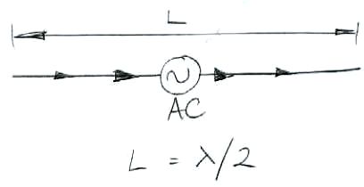
A quarter-wave antenna, as shown below, is a dipole antenna on top of a ground plane. Current enters at the base.

So far we have considered antennas from the point of view of transmitting radio waves. The same logic works in reverse when it comes to receiving radio waves. A quarter-wave antenna will provide current at its base when radio waves strike its length. In the crystal radio we are about to study, the antenna current emerges from the antenna symbol and enters the detector circuit, but there is no place where the current enters the antenna. But the current is alternating and has an average value of zero, so we have charge conservation over time in the antenna. The current is generated by the temporary and quickly-reversed displacement of charges in the antenna wire.
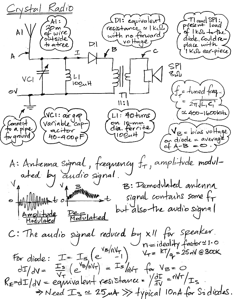
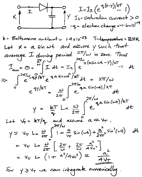
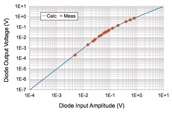
The following Pascal program integrates the sinusoidal exponential numerically, and so produces a plot of detector output versus input amplitude for many orders of magnitude. The units of amplitude are volts, and the units of the detector output are volts.
{
  Crystal Diode Response 03-MAY-12. We integrate exp(a*sin(x)) numerically so as
  to obtain the rectification response of a crystal diode. This is a Pascal source
  code file.
}
program p;

const
  dt=0.001;
  pi=3.141592654;
  a_scale=1.1;
  a_min=0.0001;
  a_max=10.000000;
  vT=0.0271; {this is kT/q for T=310K}
  fsd=10;
  fsr=1;

var
  i:integer;
  integral:real;
  a,y,t:real;

begin
  a:=a_min;
  while a<=a_max do begin
    integral:=0;
    t:=0;
    while t<=1.0 do begin
      integral:=integral+exp(a*sin(2*pi*t)/vT)*dt;
      t:=t+dt;
    end;
    y:=vT*ln(integral);
    writeln(a:fsr:fsd,' ',y:fsr:fsd);
    a:=a_scale*a;
  end;
end.
In this circuit, we use a P-type Schottky diode with IS = 3 μA to detect incoming 146-MHz radio frequency power. We connected a 146-MHz signal of known amplitude to our demodulator and measured the voltage on output of the diode detector. The plot below shows the detector output we calculate using our numerical integration, as well as our measurements.
Because the saturation current of the diode is 3 μA, its equivalent resistance for zero bias is around 10 kΩ. Compare this to several megaohms for a silicon PN diode. A PN diode made out of germanium can have saturation current as high as 10 μA, which gives an equivalent resistance at zero bias of around 3 kΩ.
The circuit below uses a transistor as demodulator and amplifier for amplitude-modulated signals in the range 500-1500 kHz. We make the antenna out of a 3-m wire wrapped a few times around the length of a 2-m bamboo pole. According to our measurements, this 1-MHz radio signals picked up by this antenna have source resistance of ≈ 25-kΩ. The impedance of C2 at 500 kHz frequencies is < 3 Ω ≪ 25 kΩ. The antenna source resistance makes an voltage divider with three components in parallel: VC1, L1, and Q1. The input impedance of Q1 for small signals is VT / IB = 25 mV / 1 μA = 25 kΩ. At frequency fT = 1/√(2πVC1L1), the impedance of VC1 and L1 in parallel will be ≫ 25 kΩ. At fT, the amplitude at point A will be roughly half the amplitude we would observe if we were to remove C2 and leave the antenna to interact only with VC1 and L1. With the transistor input resistance and the antenna source resistance matched in this way, we are extracting the maximum possible power from the antenna. The frequency fT we call the carrier frequency.
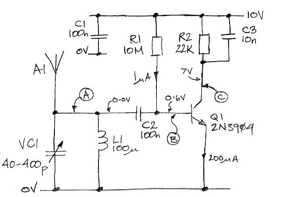
The emitter current is an exponential function of the base-emitter voltage. At room temperature, each 25-mV increase in base voltage causes the emitter current to increase by a factor of e = 2.72. When the signal on the base has amplitude ≤ 10 mVpp, the emitter current is approximately linear with signal voltage. For larger signals, the non-linearity of the transistor response becomes more prominent. Positive cycles of the input cause an increase in emitter current that is significantly greater than our linear assumption predicts, while nmegative cycles cause a decrease that is significantly less than our linear assumption predicts. As a result, the average emitter current increases with signal amplitude, even though the average value of the signal itself remains zero. The following analysis assumes our carrier signal is a square wave, which makes the calculation of the average emitter current easier.
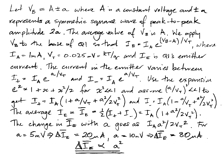
As the amplitude of the carrier signal on the base of Q1 increases, the amplitude of the carrier frequency current in the emitter increases, and at the same time the average emitter current increases. The increaes in the average current is proportional to the square of the amplitude of the signal on the base. Capacitor C3 has impedance < 30 Ω at 500 kHz. The carrier frequency component of the emitter current passes through C3. The amplitude of this current cannot be more than 400 μApp, so the carrier frequency signal at C will be < 12 mV. When the carrier signal on the base is 0 mVpp, the average emitter current is 200 μA. When the signal on the base is 20 mVpp, with IA = 200 μA in the derivation above, the average emitter current is 16 μA higher. This 16 μA flows through R1 = 22 kΩ, where it develops 350 mV. Capacitor C3 suppresses the carrier signal on C but leaves the average current signal intact. This average current signal is the demodulated signal. When receiving AM radio, the demodulated signal is the audio signal of the radio station.
There is another process in the demodulator that we must consider. Suppose the amplitude of the carrier signal on B increases from 0 mVpp to 20 mVpp instantly. The average current in the emitter increases by 16 μA. Assuming the current gain of the transistor is 200, the base current increases by 80 nA. This 80 nA cannot flow through C2 indefinitely. The only way to increase the average base current by 80 nA is to increase the voltage across the 10-MΩ base resistor by 800 mV, which would turn off the transistor. Instead, the average base current increases by 80 nA for as long as C2 can supply the 80 nA. We set up our own AM radio transmitter.
To observe the response of the demodulator, we connected a 1.4-MHz sinusoidal carrier wave to a 2-m antenna and modulated its amplitude between 0 Vpp and 4 Vpp with a square wave. Our demodulator picks up the signal with its own antenna five meters away. The voltage at C is shown below.
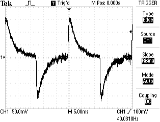
When the amplitude of the carrier steps up, the voltage at C steps down. In roughly 1 ms C reaches a minimum. The time constant of drop in C is R2 × C3 = 22 kΩ × 10 nF = 0.2 ms. This time constant acts as a low-pass filter with a corner frequency 1/2π(0.2 ms) = 800 Hz. Most voice audio is below 800 Hz, so this low-pass filter will permit talk radio to be detected. After the initial drop, C rises to its quiescent value. We expect the rise time to be C2 multiplied by the sum of Q1's base resistance and the antenna's source resistance. The base resistance is VT/IB = 25 mV / 1 μA = 25 kΩ, the antenna resistance we have assumed is 25 kΩ, and C2 = 100 nF. These give a time constant of 5 ms, which is consistent with our observation. The 5-ms time constant adds a high-pass filter to our demodulator's response. The corner frequency of this filter is 1/2π(5 ms) = 30 Hz. Most audio is above 30 Hz, so we deem C2 to be large enough. When the amplitude of the carrier decreases, C jumps up again with time constant 0.2 ms, then decays back to its quiescent value with time constant 5 ms. And so we obtain the waveform shown above.
When we deliver a modulated signal with 50-Ω source resistance directly to B we see a time constant of 2.5 ms, which is consistent with the product of C2 and Q1's base resistance without the antenna resistance. The decay time constant of the demodulator's response is one of the measurements we have made that suggests the effective antenna impedance is indeed 25 kΩ.