| Brandeis University | Physics 29a |
| Spring 2020 | Kevan Hashemi |
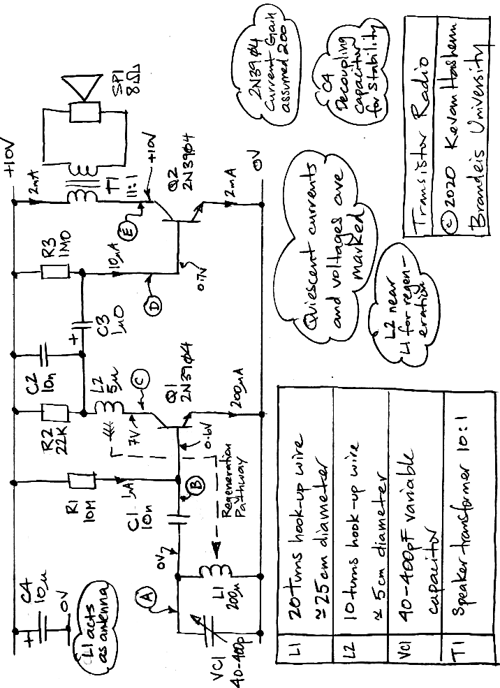
Power: Use your bench-top power supply to provide 10 V to your transistor radio. Turn your breadboard power supply off and disconnect its power cord. Do not connect anything to the breadboard power supply terminals.
Construction: Arrange components as they are presented in the diagram. Use columns for power supplies. Spread out the components so that you can see how they are connected. Use color coding for +10V (red), 0V (black), and signals (others).
Part 1: Make L1 out of twenty turns of hook-up wire 25-cm in diameter (forearm length). Give the L1 10-cm leads. Assemble L1 and VC1 on your breadboard, which together are the tuner. Deliver to A a 1.0-Vpp sinusoid with source impedance 27 kΩ. Adjust VC1 to its maximum capacitance. Increase frequency from 100 kHz to 5 MHz, observing the amplitude at A. What it the resonant frequency of your tuner? Adjust VC1 to its minimum capacitance. What is the resonant frequency now? These are the minimum and maximum tuning frequencies of your radio. Your tuning range should include 800 kHz and 1.2 MHz. With your tuner set near 1.0 MHz, plot the amplitude of A versus frequency, starting at 800 kHz and ending at 1.2 MHz. How far apart in frequency do you think two radio stations must be for your tuner to separate them from one another?
Part 2: Assemble Q1, C4, R1, and R2. Load a wire link in place of L2. Do not load C1 or C2. What are the voltages B and C? What are the quiescent currents flowing through Q1's base, collector, and emitter? Configure your function generator to produce a symmetric, 1-MHz, 10-mVpp sine wave with offset equal to the voltage you just observed on B. Connect this signal directly to the base of Q1. Adjust the offset until the average voltage at C is 7.0 V. What is the amplitude of the square wave on C? What is the gain of your amplifier at 1 MHz? Increase the amplitude of the square wave on B to 50 mV. What is the average voltage on C now? Add capacitor C2 across R2. Why does the square wave disappear from C? Why is the average voltage on C the same with and without C2? With C2 in place, plot a graph of the average voltage on C versus the amplitude of the square wave on B for amplitudes 0 mVpp to 100 mVpp.
Part 3: Disconnect your signal source from B. Load capacitor C1 so as to connect your tuning coil to the base of Q1. Adjust VC1 and look for signs of an audio signal on C. When tuned to Radio 29A, an audio signal should be visible on your oscilloscope.
Part 4: Complete the radio with all components except L2, which remains a wire link. You should be able to listen to our own Radio 29A, and maybe one or two other stations. Can you improve reception by rotating L1? By moving your hand near L1?
Part 5: Make L2, the regenerator coil, by winding 10 turns of hook-up wire on a 5-cm diameter (three fingers). Give the inductor 20-cm leads. Move and rotate L2 near L1 until you hear the speaker squealing. By adjusting L1 and VC1 simultaneously, find as many radio stations as you can. Why does the regenerator improve the performance of the radio?
Part 6: Remove each of the following capacitors turn: C1, C2, C3, and C4. Replace each component before you remove the next. For each component, note the change in the behavior of your transistor radio that occurs when you remove. Try to explain the changes to your instructor.
