| Brandeis University | Physics 29a |
| Spring 2020 | Kevan Hashemi |
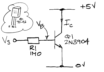
Part 1: Fetch a 2N3904 transistor. Its data sheet is on the 29A page. Build the circuit shown below, with R1 = 1.0 MΩ. Measure IC with an ammeter. Measure VB with an oscilloscope probe. Measure VS with another oscilloscope probe. Use the oscilloscope's average value measurement function to get VB to three significant figures. Vary VS from 2-15 V. Measure VS, VB, and IC at ten or more points. For each point, calculate IB.

Plot IC versus IB. What is the current gain, β, of your transistor? Plot IC versus VB, using a logarithmic scale for IC. What is the ideality factor of the base-emitter junction? What is the saturation current of the transistor?
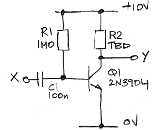
Part 2: Build the grounded-emitter amplifier circuit shown below. Use R1 = 1 MΩ and C1 = 100 nF. Choose R2 so that Y is around 5 V.

Produce a 10 mVpp (ten millivolts peak to peak) sinusoid of 10 kHz with your function generator. Apply the 10 mVpp to X. What is the amplitude of Y? What is the amplifier's gain? Is the gain inverting or non-inverting? Use the transistor equations to calculate the theoretical gain of the circuit. How well do your calculations and measurements agree?
Part 3: Estimate the maximum and minimum voltage the grounded-emitter amplifier can generate on Y. Increase the amplitude of X until the amplitude of Y no longer increases. Sketch Y. The maximum and minimum values of Y are the saturation voltages of the amplifier. Do the saturation voltages agree with your estimates?
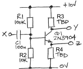
Part 4: The base resistor of a grounded-emitter amplifier must be chosen to match the transistor current gain, β, but β can vary by a factor of two from one lot of 2N3904s to the next. The common-emitter amplifier below will work for any β > 50. Build the amplifier with R1 = 100 kΩ, R2 = 10 kΩ, C1 = 100 nF. Choose R4 so that the emitter current is around 1 mA. Choose R3 so that Y sits at around 5 V.

Apply a 10-kHz sinusoid of amplitude 100 mVpp to X. What is the gain of the amplifier from X to Y? What is the gain of the amplifier from X to Z? Calculate theoretical values for these two gains.
Part 5: With 10 kHz, 100 mVpp applied to X in the common-emitter amplifier, connect 10 μF in series with 330-Ω from Y to 0 V. In this way you are applying a load of 330 Ω to the 10-kHz signal at Y, but you are applying no load to the quiescent voltage at Y. Measure the amplitude of the 10-kHz signal at Y with and without the load. Apply Thevenin's Equivalence Theorem so as to model the behavior of the 10-kHz signal on Y with one 10-kHz voltage source and one series resistor. What is this equivalent series resistance? Move the load to Z and perform the same measurements. What is the equivalent series resistance of the 10-kHz signal on Z? Why is the source resistance at Z so much lower than at Y? Remove the load from your amplifier before you move on to the next part of the Lab.
Part 6: Place a 10-μF capacitor in parallel with R4 in your common-emitter amplifier. What is the small-signal gain from X to Y with this addition? Why do you think the capacitor causes such a dramatic increase in gain?