| Brandeis University | Physics 29a |
| Spring 2020 | Kevan Hashemi |
Derivations: You are welcome to perform your derivations outside laboratory hours, but be sure to have them written in your notebook.
Frequency: We will use ω to denote frequency in radians per second (rad/s), and f to denote frequency in cycles per second (Hz).
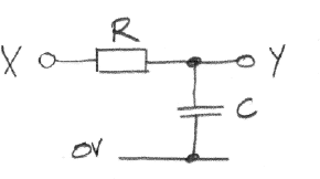
Part 1: Derive the complex gain of the following low-pass filter circuit as a function of angular frequency, ω. Calculate the filter's corner frequency, fC, at which the filter gain is 1/√2. Calculate the magnitude and phase of the gain at fC, 10fC, and fC/10.

Construct the low-pass filter using 10 kΩ for R and one of our variable, air-gap capacitors for C. Set the variable capacitor to its maximum, which should be around 400 pF. Assuming 400 pF, calculate an estimate of fC. Apply a sinusoid of this frequency to X. Display X and Y on your oscilloscope. Adjust the frequency until the magnitude of the gain is 1/√2. Sketch X and Y. Measure the phase of the gain. Measure gain and phase at 10fC and fC/10. From your measurement of fC, deduce the actual capacitance of the variable capacitor.
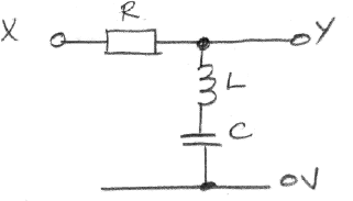
Part 2: Derive the complex gain of the following notch filter circuit as a function of angular frequency, ω. Calculate the frequency, fR, at which the theoretical gain is zero. We call this the notch filter's resonant frequency.

Wind forty turns of hook-up wire on a 50-mm long, 10-mm diameter ferrite core. Do not attempt to wind neat side-by-side turns along the core. Allow the turns to overlap one another. Construct the notch filter using your forty-turn coil, a 1% 470-pF capacitor, and a 1-kΩ resistor. Apply a sinusoid to X. Vary its frequency from 1 Hz to 1 MHz and back down again. Now go through the range again, picking frequencies at which to measure the magnitude and phase of the complex gain. Plot the magnitude and phase versus frequency. Use a log scale for frequency, but a linear scale for gain and phase. What is the inductance of your forty-turn coil? What is the accuracy of your measurement?
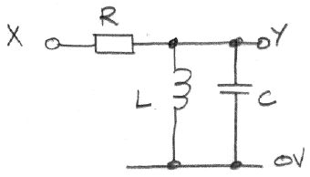
Part 3: Consider the tank tuner circuit below. Calculate the frequency, fR, at which the theoretical gain is one. The quality factor, Q, of the tuner is the ratio fR/(f1−f2), where f1 and f1 are the two frequencies at which the magnitude of the filter gain is 1/√2 of its maximum. Derive an expression for Q in terms of L, C, and R.

Build the tank tuner using your forty-turn coil, a 1%-accurate 470-pF capacitor, and a 10-kΩ resistor. Apply a sinusoid to X and plot of the magnitude and phase of the filter's gain versus frequency. Measure fR and Q. Compare your measurements to your calculations.
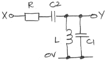
Part 4: Build the split-capacitor tuner circuit shown below, with R = 100 Ω, C1 = 1.0 nF, C2 = 100 pF, and your forty-turn coil for L.

Apply a sinusoid to X and plot the tuner's frequency response. Be sure to measure the amplitude of X and Y at each frequency. Measure the frequency, fR, at which the gain is a maximum. Measure the quality factor, Q, as we defined it for the tank tuner. How is it possible for a circuit made of passive components to have a gain greater than one?