| Brandeis University | Physics 29a |
| Fall 2019 | Kevan Hashemi |
Part 1: Pick a resistor between 1 kΩ and 10 kΩ. Measure its resistance with an ohmmeter. Connect the positive terminal of your power supply to the input of a digital ammeter. Connect the output of the ammeter to one end of your resistor. Connect the other end of the resistor to the negative terminal of your power supply. Connect a digital voltmeter across the resistor only. Be sure, when you connect the voltmeter, that you have it configured to measure voltage rather than current, or else you may blow the fuse inside the meter.
Increase the power supply voltage from 0V to 15V. Plot a graph of voltage versus current. The plot should span the range of your adjustment and include at least six points. Does the resistor obey Ohm's Law? Fit a straight line to the graph (use a ruler and graph paper, or a calculation in a spreadsheet, whichever your prefer). How does the slope of the graph compare to the resistance you measure with an ohmmeter? What is the intercept of your graph? Is the intercept consistent with Ohm's Law?
Part 2: Replace the resistor of Part 1 with a miniature incandescent light bulb. Increase power supply from 0 V to 6 V in steps of 0.5 V. At each voltage, measure the supplied current. When the bulb is glowing, wait until the current reaches an equilibrium value, which might take thirty seconds. Be sure not to apply more than 6 V to the bulb, or its filament may burn out. Plot a graph of voltage versus current. Does the light bulb obey Ohm's Law?
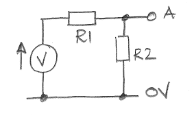
Part 3: Pick two resistors R1 and R2 between 1 kΩ and 10 kΩ. Measure their values with an ohmmeter. Construct the voltage divider shown below.

Set the voltage, V, to 10 V. Check its value with a voltmeter. Use Ohm's Law to calculate the voltage A. Measure the voltage at A. This voltage is the open-circuit voltage for point A. Connect an ammeter from A to 0 V. What is the voltage on A with the ammeter connected? Is this voltage small enough that we can treat it as 0 V? If so, then the current through the ammeter is the short-circuit current for A. Leaving both R1 and R2 in place, connect a resistor roughly one half the value of R2 from A to 0 V. What is the voltage at A now? Repeat with a resistor roughly double the value of R2.
At this point, you have connected four different loads to point A: 0 Ω, R2/2, 2R2, and ∞ Ω. Recall Thevenin's Equivalence Theorem and calculate the single voltage and single resistance that will produce the same behavior as point A with respect to 0 V. Build the equivalent circuit. Apply the same loads to the output of the equivalent circuit as you did to the original circuit. Does the equivalent circuit behave in the same way as the voltage divider for all four loads?
Part 4: Replace R2 of Part 3 with a light-sensitive resistor, which we call a photoresistor. When you shine light on the photoresistor, does A increase or decrease? By measuring A, determine the approximate resistance of the photoresistor in darkness and in bright light.
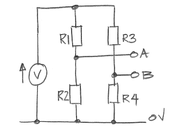
Part 5: Construct the dual voltage-divider below, which is a circuit called a Wheatstone Bridge. Pick four resistors R1 through R4, not all of the same value, but all between 1 kΩ and 2 kΩ. Use V = 10 V. Measure their resistances with an ohmmeter.

Use Ohm's Law and your measurements of the resistors to calculate the voltage between A and B. Calculate the voltage and series resistance that produce the same open-circuit voltage and short-circuit current as points A and B. Calculate the current that should flow from A to B if you connect them with a wire. Measure the open-circuit voltage difference between A and B. Measure the short-circuit current between A and B.
Replace R4 with the variable resistor on your breadboard, or with a potentiometer (a variable resistor) taken from the component draws. Calculate the value of R4 that will make A and B equal. Adjust the variable resistor until A and B are indeed equal. Remove the variable resistor from your Wheatstone Bridge and measure its resistance. Is your calculation consistent with your measurement?