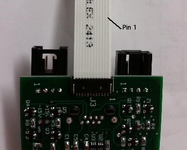
Figure: A right handed flex connector. When the opening is away from you and the pin connectors are up, pin one is on the right.
| Nomenclature | Acceptable Orientations |
The problem of confusing the various types of ribbon cable connectors (Flexible Flat Cable, or "FFC") has cost us countless hours of productivity over the years. We have come to the conclusion that there is no convention that will cover all use cases and that each implementation must be thought out thoroughly to avoid confusion. We try to establish consistent use in new Small Wheel electronics to avoid hours of troubleshooting later.
There are many factors to consider with cable orientation:
The problem is not as trivial as it would first appear.
Rule: All ICX-424 minimal heads must be interchangeable. All ICX-424 devices must maintain the same pinout on flexible connectors.
Recommendation: No reversible (top and bottom contacts) flexible connectors should be used.
Rule: The Bar Head (A208201B) sets the standard for the orientation of new Small Wheel connectors.
We look down at a camera board with a connector on top. We orient the camera connector facing left. Both connectors are right angle with the pin connections on top. In this orientation, pin 1 is away from us. (In the image, pin 1 is on top, and pin 12 is on the bottom.) We will make all image sensors and minimal heads compatible with this orientation.
Look at a flex connector with the connector opening facing away from you and the pin connections on the near (top) side of the cable. If pin 1 is on the left you have a "left handed" connector. If pin one is on the right you have a "right handed" connector.
A left-handed footprint with pin connections on top is the same as a right-handed footprint with pin connections on the bottom.
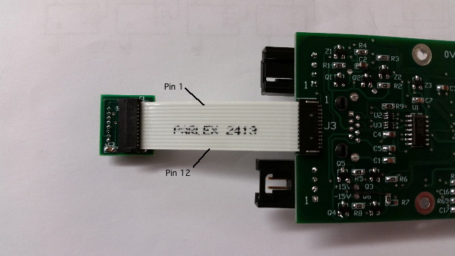
Convention: The connector on the A208201B board above is referred to as a "right-handed" surface-mount-pinout. We abbreviate this "FLEX-12-RSR" for flex, 12-pin, right-angle (R), surface-mount (S), right-handed (R). The connector on the minimal head is a "left-handed" orientation of a through-hole connector.
| Footprint Types | ||
|---|---|---|
| Variable | Options | |
| Orientation | L = Lefthanded | R = Righthanded |
| Angle | S = Straight Up | R = Right Angle |
| Mounting Type | S = Surface Mount | T = Through Hole |
| Connector Types | ||
|---|---|---|
| Variable | Options | |
| Shield | S = Shielded | U = Unshielded |
| Angle | S = Straight Up | R = Right Angle |
| Mounting Type | S = Surface Mount | T = Through Hole |
| Contacts (RA only) | T = Top | B = Bottom |
| Board | Connector | Type | Pin Connections | Footprint |
| Camera Head | CCD connection | Surface Mount | Top | Right-Handed |
| Camera Head | CCD connection | Surface Mount | Bottom | Left-Handed |
| ICX-424 Minimal Head | Camera Connection | Surface Mount | Top | Left-Handed |
| ICX-424 Minimal Head | Camera Connection | Surface Mount | Bottom | Right-Handed |
Recommendation: When a board has different versions requiring different footprints, a table should be placed on the schematic dictating the different footpritns and parts required.
Conventions for light source pinouts are yet to be determined.