Mask Assembly Manual

© 2008 Alex Asen, Brandeis University.
www.bndhep.net

Contents

Introduction
Assembly

Introduction

This manual briefly describes how to assemble RASNIK Bar Masks.

diagram

Parts:

  1. Box
  2. Mask, Size #340
  3. Front Spacer, about 4.5mm thick
  4. Diffuser
  5. Middle Spacer
  6. Electronics, A2045
  7. Lid
  8. Base
  9. Screw Pan Philips M3x8, McMaster 92000A118
  10. Dot Marking Mask Orientation
  11. O-Ring, Viton AS568A-005, McMaster: 9464K105
Figure 1: Diagram of a Black Bar Mask.

Assembly

Before you epoxy anything, run through all the steps to make sure the parts you are working with fit together properly.

Step: 1
  1. Lay a piece of plastic that epoxy will not stick to such as an overhead transparency on the table .
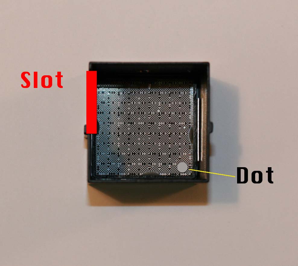
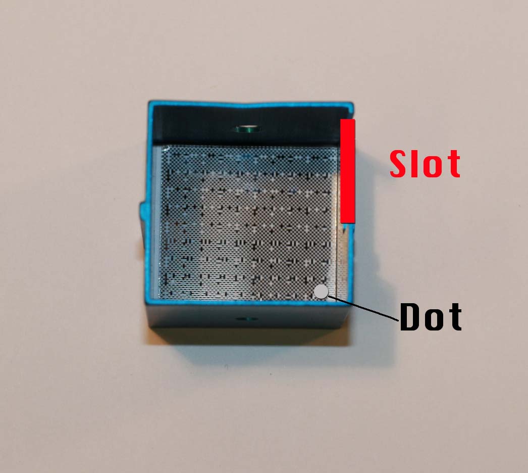
  2. Notice the silver dot on the front of the Mask. Place the Mask front down on the table. The silver dot should be touching the table and should be in the bottom right corner when looking down at it.
  3. Place the Box on top of the Mask. The orientation of the Box relative to the gray dot on the Mask is easiest to figure out by looking at an already made sample or by following the pictures below. The orientation will be different for the Black and Blue Masks.


  4.        

    Figure: Images showing the correct orientation of the mask and mask body prior to gluing.
    Note that the dot is actually on the underside of the mask during construction.


  5. Place an aluminum shim on each of the four sides of the Mask, wedged between the Mask and the Box. You may have to cut the the shims in half with scissors so that they do not overlap the screw holes in the Box.
  6. Using 3M, DP-460 24hr epoxy and a syringe, place a modest amount of epoxy in the corners of the Box and where the aluminum shims meet the Box and Mask.
  7. Place the Front Spacer in the Box. The Front Spacer should be about 4.5mm thick. The Spacers vary in width, and incorrectly sized pieces can create problems later when aligning the screw hole in the Middle Spacer. Also, In-bar masks have front spacers of a different width.
  8. Allow the epoxy to set for 24 hours.

Step: 2

  1. Turn the Box over and use a razor blade to scrape off any epoxy that dripped onto the front of the Mask. Also check that the gray dot on the Mask is oriented correctly.
  2. Place the Diffuser in the Box. The white side should face down towards the Mask and the clear side should face upwards.
  3. Put a modest amount of epoxy around the the Diffuser. Do not cover the entire perimeter of the diffuser, just the corners and a dab in the middle of each side.
  4. Place the Middle Spacer in the Box. Be sure that there is enough clearance around the screw hole in the Box so that the head of the Screw can sit flush against the Box.
  5. Use a long screwdriver to hold the Screw in place while fastening a O-Ring to the under side. Check that the Screw sits flush and does not overlap the Spacer.
  6. Allow the epoxy to set for 24 hours.

Step: 3

  1. Test the A2045 circuits. If you turn off the lights in the lab, the infrared LEDs emit a red glow visible to the naked eye. There is no easy way to remove bad electronics once they are epoxied in, so it is important to test first.
  2. Epoxy the A2045 in place.
  3. Allow the epoxy to set for 24 hours.

Step: 4

  1. Epoxy the lid onto the Box. The lid is not a square. Find the long side and orient it so that it does not interfere with the Base in the next step.
  2. Allow the epoxy to set for 24 hours.

Step: 5

  1. Slide the Base onto the Box.
  2. Position two blocks of scrap so the Base rests on them and Screw coming out the bottom is floating.
  3. Epoxy the Base in place.
  4. Allow the epoxy to set for 24 hours.