Pigtailed LED Assembly Manual
© 2011 Michael Collins, Brandeis University.
www.bndhep.net

Pigtailed LED
Introduction
This manual describes the process of building a pigtailed LED for use with a modified Quad LED Head (A2051). We begin by preparing optical fibers and gluing them to LEDs. The LED is then soldered to a wire connector which regulates the voltage supplied to the LED. Finally, we pot the pigtailed LED in epoxy for durability and to reduce light leakage at the fiber-LED interface.
Procedure
- Begin by preparing lengths of CK-40 1.0mm optical fiber for assembly. Cut fiber to 2cm over desired final length using diagonal cutters. We have so far successfully used lengths from 2-8.5m. As length increases, we expect diminished brightness of the fiber tip. For cutting long sections of fiber, it may be helpful to lay out measuring marks on the floor. Take care to not place excessive tension on the fiber as this may cause permanent deformation.
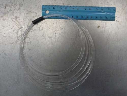
- Coil the cut section of optical fiber. Coils with approximately 15cm diameter and 15cm long free ends are the most convenient to work with in the following steps. Bind the coil with gaffer's tape or masking tape. Other methods can be used, but take care to not crush the fibers.
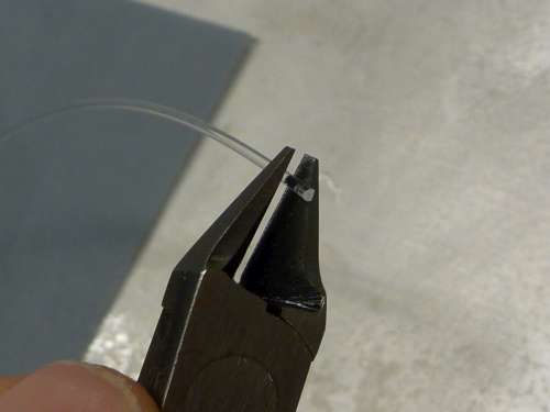
- Use a pair of diagonal cutters to trim the ends of the fiber. For the best cut, face the angled section of the cutters toward the scrap end of the fiber. Take care to make a perpendicular cut.
- Take three sheets of polishing paper (gray, pink, and green) and use a sponge to lightly moisten the plastic side of each. Place them, abrasive-side-up, on a flat and smooth metal surface several inches apart from one another. The water droplets cause them to firmly stick to the metal.
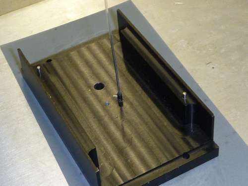
- The polishing jig is a black piece of aluminum with a rubber sleeve connected to a hole through the aluminum base (each 1.0mm inner diameter) near the center which holds fibers perpendicular to the polishing paper. We use three 6"x3" sheets of 3M polishing paper: 15 micron (gray), 3 micron (pink), and 1 micron (green). Place the jig on the gray polishing paper (15 micron), and insert the trimmed end of the optical fiber into the rubber sleeve until it is in contact with the paper as shown above. Grip the coil of fibers to keep it off the table and other equipment. Pinch the end of the fiber with the thumb and forefinger just above the sleeve and apply downward pressure as shown below. Begin tracing large figure eights with the fiber end over the paper. The jig moves with the fiber helping you maintain perpendicularity and avoid rounding off the corners of the fiber. Sixty figure-eight passes should bring fiber tip to a smooth and uniform circle.
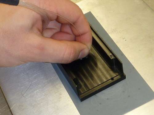
- Visually inspect fiber tip for uniformity of polishing. Remove any plastic filaments or particles that may cling to the fiber tip. When the fiber is a clean and uniform circle, repeat the polishing procedure on the pink polishing paper (3 micron), then finally green (1 micron). After approximately sixty figure-eights at each grit, the fiber tip should appear highly polished and the fiber should readily transmit light.
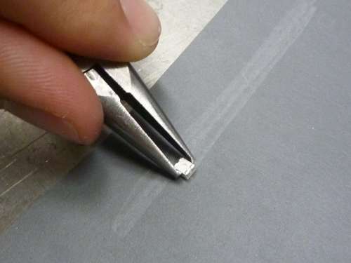
- Set polished coils aside and prepare the Optek 624nm surface mount LEDs (OVSA1SBC2R) for assembly. These LEDs are packaged in transparent epoxy which is difficult for adhesives to cling to. To ensure proper adhesion in the glue-up, we must scuff the surface. Lay out a sheet of 320 grit (36 micron) sandpaper and use a pair of pliers to hold the LED, light-emitting side down, against the sand paper. Make about eight three inch passes across the sandpaper as shown above. It is important to use even pressure to avoid sanding one side more heavily than another. When finished, the LED should appear cloudy and scratched. Use 190 proof ethyl alcohol to clean the scuffed surface of debris. Inspect to make sure that the LED surface is flat and parallel to its base. In the photo below, the right-most LED has been properly scuffed, while the center LED is as it appears from the factory.
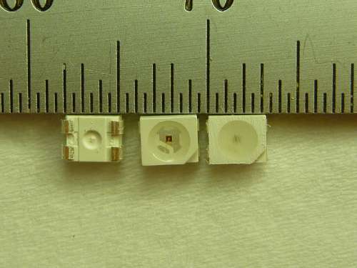
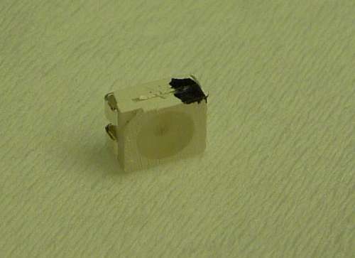
- Each LED has four contacts designed for surface mount assembly (these contacts can be seen above in the left-most LED, which faces away from us). Three are anodes and one is the cathode. At this point, before the LEDs get covered in glue, it is a good idea to mark the cathode. Each LED has one corner shaped at a 45 degree angle. The cathode is the contact directly across from this corner. Mark this corner with a black marker as shown below.
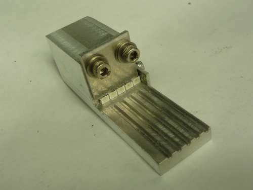
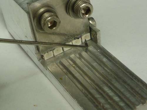
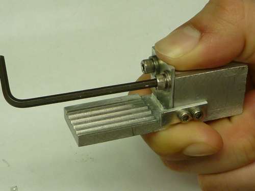
- We use a jig to aide the gluing of the fibers to the LEDs. It is shown above, holding five banked LEDs. It is capable of holding five fibers at a time though it is fine to use it for fewer. Insert up to five LEDs, scuffed-sides-out, into the channel of the jig. Use a pick to ensure that the right-most LED is tightly against the wall of the jig and that each subsequent LED is tightly banked against its neighbors. Ensure that each LED is pressed flat against the back wall of the jig. Alternatively, an L-shaped tool could be made out of a piece of metal to facilitate this step by pressing all LEDs into proper position at once. With all LEDs in proper position, apply downward pressure to the locking gate and tighten the locking screws as shown below.
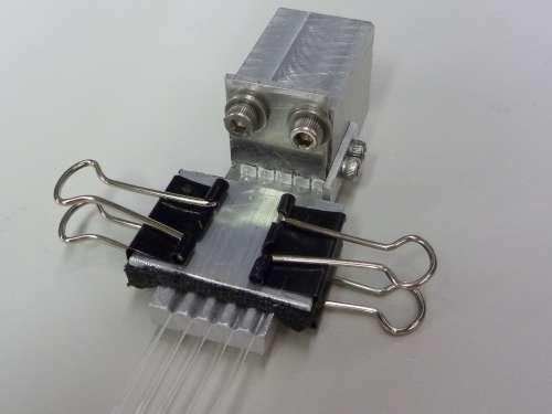
- Insert fiber ends into the fiber grooves of the jig. Each tip should align with an LED. Use a pair of binder clips to secure the clamp plate to the jig, foam-side-down, to lock the fibers into place as shown above. Do not allow the clamp plate to pass over the edge of the jig which the fibers enter at; otherwise, the fibers may be permanently bent. At this point, it is helpful to slightly open the binder clips and push each fiber firmly against its LED. This ensures good contact and creates friction which facilitates final alignment of each fiber.
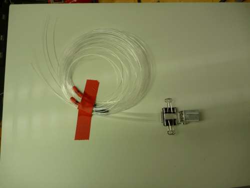
- Lay the jig and fiber coils onto a flat, moveable surface such as a piece of cardboard or sheetmetal. Tape the coils down and incline the board to approximately 45 degrees with the jig below, coils above. This position helps the adhesive stick to both the fiber and LED without running onto the jig, while making it easier to manipulate fiber tips. This is the position in which the adhesive cures.
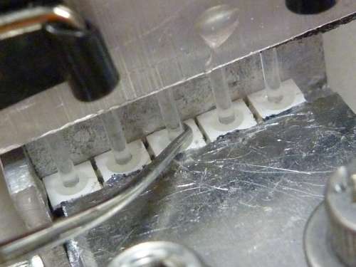
- With good pressure between each LED and fiber, use a pick as necessary to align each fiber tip with the center of each LED, being careful to not scratch the fibers. It may be useful to shine a light into the opposite end of each fiber to visually check concentricity at the fiber-LED interface. The setup shown below is ready for glue-up.
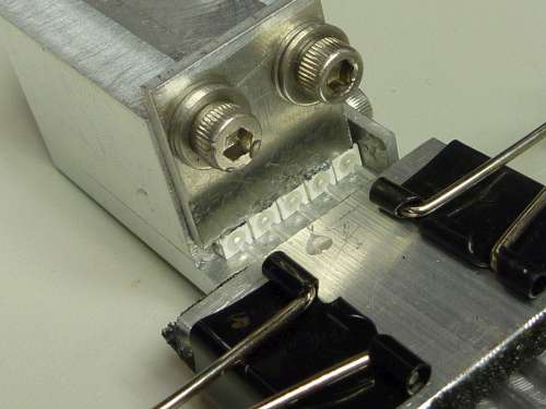
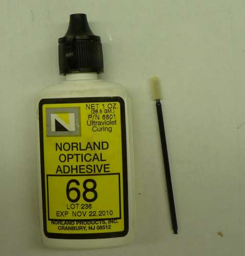
- Using a small foam applicator, dab a very small amount of Norland Optical Adhesive 68, an optical grade, UV-hardening adhesive, onto each fiber-LED interface. There will be two more layers of adhesive applied, so it is fine to use as small of an amount as is possible. The adhesive should not contact anything but the tip of the fiber and LED. Position a UV lamp 4" directly above the LEDs and switch it on. Allow adhesive to cure for 15 minutes as shown below.
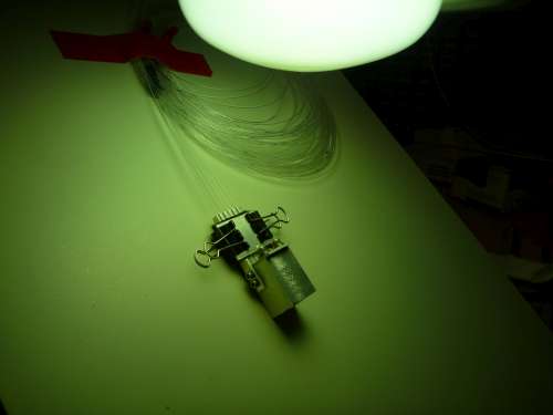
- Note that the UV lamps contain a safety circuit which prevents them from being turned on while hot. One should move the light away from the jig without switching it off, to avoid having to wait ten minutes to be able to turn it back on. Remove lamp and apply a second coat of optical adhesive to fiber tips. This should be a slightly larger drop. The adhesive does not adhere well to aluminum, so if a bit gets on the jig, this is not a huge problem. Be particularly careful to avoid gluing LEDs to each other. Immediately after the adhesive has been applied, apply UV light. Failure to do so results in the adhesive dripping down the LEDs and pooling at the base of the jig. Allow to cure for twenty minutes, with the lamp 4" away. It is not recommended that the LEDs be exposed to the lamp longer than this as excessive heat or UV radiation may damage the adhesive.
- After switching off lamp, allow jig to fully cool. Loosten the locking screws, then remove the clamp plate. The fibers and LEDs should come out of the jig easily. If any are accidently glued to the jig, use a pick to gently pry the LED off of the metal. The adhesive should peel off of the aluminum without much hastle. At this stage, the fiber to LED connections are very fragile. It is important that they be handled very gently. Two types of failure are possible. The first is that the glue fails at the LED surface. This is unlikely if the LED was properly scuffed. A more likely failure is that the fiber will slip out of the adhesive that was securing it. Because of this, the joint is particularly sensitive to torque. Handle the fiber by holding onto the coil, never grabbing it by the LED unsupported.
- Inspect fiber-LED connection. Check for glue on LED contacts. If there is any present, a file may be used to expose bare metal.
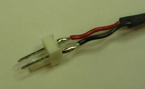
- Place coil aside and cut a 20cm length of 24AWG twisted wire. Solder a molex connector to one end, observing correct placement of the black and red wires with respect to the connector's tab. An image of proper position is shown above. Use two pieces of small shrink tube to strengthen these joints and insulate them from one another.
- At the other end, slide on a 5cm length of .157" heat-shrink tubing. Untwist the wires and slide a 1cm length of heat-shrink tubing over the black wire.
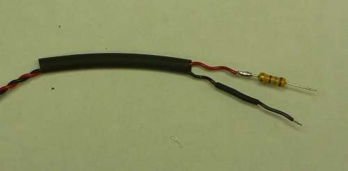
- Cut 2cm off of the red wire and strip both wires' ends. Solder a 180 ohm, 1/2W resistor in series with the red wire and trim the free lead so that the black wire and resistor lead reach the same length.
- Now attach this assembly to the LED. The black wire attaches to the cathode. The resistor lead attaches to either of the contacts on the opposite side, though the one diagonally opposite is recommended as this may make sliding the heat-shrink over the LED easier in the next step. The adhesive used on the fiber is fragile and sensitve to heat. Therefore, it is important to tin the wire, then bring the wire with molten solder directly to the contact and immediately remove the iron. Transferring any more heat than necessary to the LED may result in joint failure. Slide the small heat shrink down the black wire and shrink with a soldering iron, not a heat gun. The result should look something like the image below, but note that there is more adhesive connecting the fiber to LED than is usual.

- Now slide the .157" shrink tube up over the LED. It should extend 1.5 cm beyond the fiber-LED interface. Use a soldering iron to heat the shrink tube near the resistor on the side away from the fiber. Shrink just enough to constrict the tube but not so that it forms an air-tight seal.
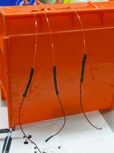
- Secure the coils so that the LED ends hang freely downwards away from the coil and any other objects as shown above.
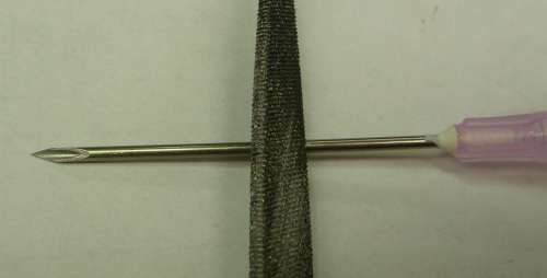
- Set fiber aside and use the corner of a file to cut through half of an 18ga needle 2cm from its base. Snap off sharp end and discard. Fill syringe with potting epoxy such as ResinLab EP965LVLX.
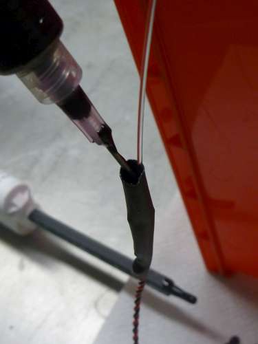
- Inject potting epoxy down into the mold formed by the heat shrink tubing of each assembly and fill to the top. A few minutes later, the low-viscosity epoxy will have settled deeper into the tube. Refill to the top once or twice as necessary. Allow 24 hours for a full cure. At this point, the fiber-LED joint is quite robust.
- To finish the assembly, use a heat gun to shrink any shrink tube covering the wires which was not filled by epoxy.
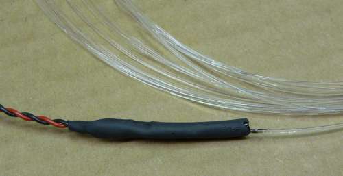
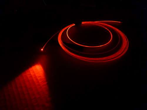
- Below is a photo (f/3.3, 1/8sec.) of a completed pigtailed LED connected to an A2051 being illuminated. In a dark room, the entire fiber length becomes visibly red when the LED is on. In a well-lit room, the fiber tip still appears very bright to the human eye, but light from the length of the fiber will not be as noticeable if at all.
