
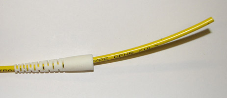
Figure: Assembled Fiber With FC Connector.
Here is an overview of fiber jumber assembly by hand. For a description of the same procedure, but with the help of a polishing machine, see Fiber Polisher Manual. Up until the actual polishing, however, the hand and machine procedures are the same.

The jacket is the yellow part of the fiber, with glass fiber strands inside for more protection. The white component is the lateral strain relief. There is an inner axial strain relief that holds the jacket to the connector. The optical fiber itself is, in this case, a 125-μm glass fiber with a 62-μm core of higher refractive index that carries light. The fiber is glued inside a zirconia ferrule with a 126-μm bore, and polished optically flat at the end. This particular connector is called an "FC". It is used with multimode fibers. This one is "un-keyed", meaning we can connect it to an "FC Union", and thus to another FC plug, without worrying about the connector rotation.
To assemble the above termination, we begin by stripping and cutting to produce the following.

The lateral strain releif goes on first.
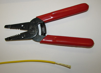
We can use ordinary wire strippers to remove the plastic jacket.
But we need some sharp, steel scissors to cut the glass fiber filler inside.

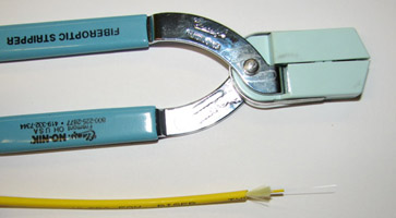
We remove the inner jacket from the optical fiber using a special tool. The figure below shows one that we find reliable. It has a directional arrow on them. Be sure to check the strippers for debris before using them. We have others that are simpler and just as functional.
The axial strain relief is a metal collar we must crimp to the fiber jacket at its narrow end. We will crimp the larger end to the connector later. You have to wiggle the jacket to get it into the strain relief.
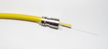
Note that the slotted slide goes on first. Make sure to trap all the insulation between the cable and the crimp. The insulation ensures the crimp is tight enough.
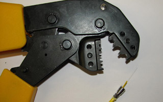
Use the smallest notch on the crimping tool to attach the crimp to the cable. The crimpers should be adjusted to maximum tightness. The crimp get a bit mangled looking, but at lighter settings was not reliable attached.

Inject glue into the fiber bore hole that runs through the connector's zirconia ferrule. Use a syringe and needle. We use black DP460 because it gives us a 60-minute working life and is easy to see.
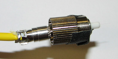
The fiber should stick out 5mm or more. There will be glue visible on the fiber, and a small island of it around the place where the fiber emerges from the tip of the ferrule.
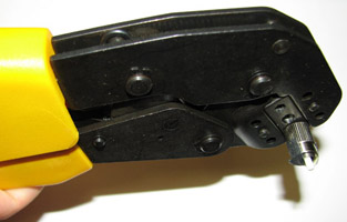
We crimp the strain relief to the knurled surface of the connector. This crimp will hold the jacket, and therefore the optical fiber, as we manipulate the cable when in use, thus avoiding stress upon the glue joint within the connector. Use the largest notch on the crimpers to perform the crimp. Test the crimp by holding the connector in one hand and the cable in the other. With an eye on the fiber sticking out the top of the connector, tug on the cable. If everything is crimped securely, the fiber will not move. Allow twenty-four hours for the glue to cure.
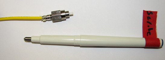
Scratch the side of the fiber close to the connector, just above the glue. Pull the fiber away from the connector and it should snap cleanly. You don't want the fiber to shatter in such a way that an irregular perimiter penetrates into the connector ferrule, because you cannot polish anything that is beneath the end of the zirconia.
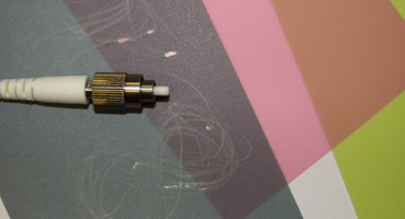
We use three grates of polishing paper. We begin with 15-μm grit, a larger sheet held in one hand in the air, and we polish the protruding tip of the glued fiber on this paper. We have no support behind the paper because we do not want to snap the end of the fiber. If we snap the fiber, it will shatter inside the ferrule and we will have to start again. We continue polishing, by moving in circles or figure-eights, until only a gray shadow of the glue remains, and the fiber protrudes only a fraction of a milimeter. Now we move to 3-μm diamond grit lapping paper on a rubber pad that is in turn placed upon a firm surface. Before we place the fiber on the finer grit, we immerse it completely in water and blow clean with compressed air. We place the connector in a polishing puck and polish on the lapping paper in twenty figure-eights. We wash again and blow dry before moving on to 1-μ grit lapping paper. Again, we polish with twenty figure-eights.
We wash, blow dry, and inspect in a fiberscope. A fiberscope is a specialized microscope that illuminates the end of the ferrule so we can see scratches. There should be no scratches visible on the tip of the fiber. The glass must be optically flat for the most efficient transfer of light from this fiber to another.