Alignment Electronics for the New Small Wheel
nSW Review
CERN, 12-MAR-15
Kevan Hashemi
Physics Department
Brandeis University
http://www.bndhep.net
Contents
Alignment System
Alignment Electronics
Requirements of nSW
Obsolete Image Sensor
Existing H-BCAM
Existing Bar Head
Linearity of ICX424AL BCAM
Changes Required by ICX424
Simulated nSW Doses
Expected Doses and Test Facilities
Ionizing Radiation Tolerance
Neutron Radiation Tolerance
Single Event Upset Tests
Conclusion
Appendix: Linearity with Quadruple-Pixel Readout
Appendix: Energy Spectrum of Photons and Neutrons
Appendix: Dose Rate Spectrum of Photons and Neutrons
Appendix: Dose Map from Background Group
Alignment System
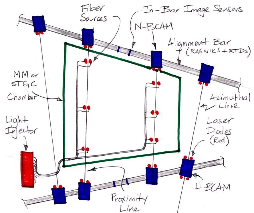
Alignment Electronics
Requirements of nSW
- Triple the number of light sources as the old Small Wheel.
- Wider field of view required by cameras to view more light sources.
- Must work with only the existing LWDAQ cables from USA15.
- Ionizing and neutron doses 5× higher.
- BCAM accuracy 5 μrad relative, 50 μrad + 20 μm absolute.
- RASNIK accuracy 5 μm relative.
- Bar temperature measurement accuracy 0.1°C relative.
- Must allow for light source flash times up to 10 ms.
In the Alignment Bars, and for N-BCAMs and H-BCAMs, we address these challenges as follows:
- Use ICX424: wide field of view, superior tracking accuracy to TC255.
- Blue LEDs instead of red for RASNIK masks: radiation tolerant.
- Optical fibers to deliver light to numerous sources.
- Non-volatile PLDs: more multiplexing, power-up reset, radiation tolerant.
- JFET analog switches: radiation tolerant.
- Bipolar power switches: radiation tolerant.
- LM6172M op-amp for amplifiers: radiation tolerant.
- LM4050 voltage references: radiation tolerant.
Obsolete Image Sensor
- Texas Instruments stopped making the TC255P ten years ago.
| Property |
KAC00401 |
ICX424AL |
TC255P |
| Manufacturer |
Eastman Kodak |
Sony Semiconductor |
Texas Instruments |
| Technology |
CMOS |
CCD |
CCD |
| Sensor Area |
5.1 mm × 3.3 mm |
5.8 mm × 4.8 mm |
3.4 mm × 2.4 mm |
| Pixel Dimensions |
6.7 μm × 6.7 μm |
7.4 μm × 7.4 μm |
10 μm × 10 μm |
| Fill Factor |
Estimate <80% |
Observe ≈100% |
Observe >90% |
| Uniformity of Dark Current |
10% |
1% |
1% |
| Uniformity of Sensitivity |
10% |
1% |
1% |
| Package Size |
12.2 mm × 12.2 mm |
12.2 mmm × 9.5 mm |
10.0 mm × 10.0 mm |
| Control Interface |
Volatile Configuration Bits |
Clock Voltages |
Clock Voltages |
| Output Format |
Serial Digital |
Pixel Voltages |
Pixel Voltages |
| Price |
≈$40 |
$40 |
≈$40 |
Table: Comparison of Image Sensors.
Existing H-BCAM
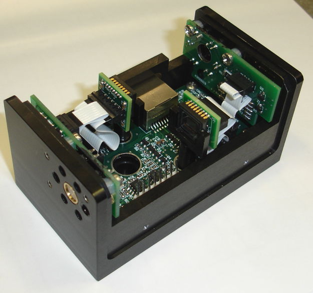
Figure: The H-BCAM. Installed and operating in HIE-ISOLDE.
Existing Bar Head
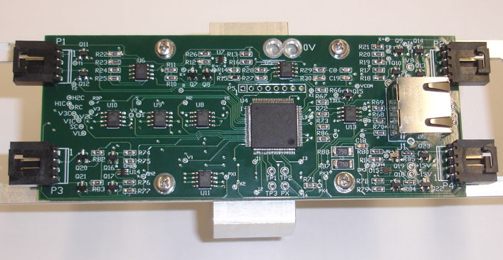
Figure: The Bar Head (A2082A). Provides connection to four ICX424 image sensors, four 100-Ω RTDs, and four Blue Nine-LED Arrays.
Linearity of ICX424AL BCAM
Figure: ICX424 BCAM Non-Linearity Across Entire Field of View. Pixels 7.4 μm square. Residuals in microns on sensor plotted versus stage position. Image sharply-focused. Two red lasers at 3.1 m on 300-mm stage, camera focal range 3 m, lens focal length 48 mm, camera V0359. Repeat with poorly-focused spot residuals remain 0.2 μm rms.
Changes Required by ICX424
- ICX424 is a three-phase device, while TC255P was single-phase.
- ICX424 permits pixel binning, requires double-clocking.
- ICX424 camera logic 4× more complex than TC255P camera logic.
- All nSW devices will use non-volatile, programmable logic devices (PLDs).
- ICX424 full-resolution image 4× larger than TC255 image.
- Original LWDAQ Driver (A2037) too slow for ICX424 images.
- Need a VME-resident version of our faster LWDAQ Driver (A2071).
- Will build 20 fast LWDAQ Drivers (A2071V).
- Original TCPIP-VME Interface (A2064F) too slow for ICX424 images.
- Will build 3 fast, new TCPIP-VME Interfaces.
Simulated nSW Doses
Figure: Simulated Dose Rate versus Radius in nSW After Ten Years. Assume luminosity 5×1034 1/cm2s, beam energy 14 TeV, run time 107 s/yr. Unit 1 Tn means 1012 1-MeV eq. neutrons/cm2. Unit 1 Gy means 1 J/kg ionization energy in Si. Doses we designed for in oSW were 20 Gy and 0.8 Tn.
Expected Doses and Test Facilities
Expect the following doses after ten years running in nSW.
- BCAM image sensors at ≥ 2.2 m ⇒ ≤ 120 Gy and ≤ 5.5 Tn.
- BCAM lasers at ≥ 2.2 m ⇒ ≤ 120 Gy and ≤ 5.5 Tn.
- Bar image sensors at ≥ 3.1 m ⇒ ≤ 60 Gy and ≤ 3.0 Tn.
- Bar light sources at ≥ 2.2 m ⇒ ≤ 120 Gy and ≤ 5.5 Tn.
We have made repeated use of the following test facilities:
- Our own 14-50 keV continuous x-ray source (live up 2000 Gy).
- Our own Cesium-137, 500-keV γ source (live up to 500 Gy).
- Proton-lithium neutron source at UMass Lowell (live up to 1.8 Tn).
- Fission neutron source at UMass Lowell (passive up to 16 Tn).
Ionizing Radiation Tolerance
- ICX424 dark current increases linearly with ionizing dose.
- With quadruple-pixel readout, get sharp images at 20 °C after 500 Gy.
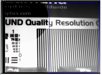
Figure: ICX424 Quadruple-Pixel Image after 450 Gy. Circle is tungston sphere absorber.
- Luxeon Z blue LED unaffected by 1 kGy.
- SW06 analog switch unaffected by 2 kGy (CERN Tests).
- LC4064ZC logic chip fully functional after 1 kGy.
- Logic quiescent current increases from 3 mA to 4 mA after 1 kGy.
- Note: TC255P was barely affected by 1 kGy, still functional after 10 kGy.
Neutron Radiation Tolerance
- Three neutron tests at University of Massachusetts, Lowell.
- Doses 2.2 Tn, 1.8 Tn, 14 Tn, and 16 Tn.
- ICX424 dark current increases linearly with neutron dose.
- Get sharp, full-resolution ICX424 images at 20°C after 14 Tn.
- With alternate-line readout, expect tolerance of >28 Tn.
- To do: add alternate-line readout to LWDAQ driver firmware.
- Blue LEDs unaffected at 16 Tn, will use for RASNIK masks.
- Deep red LEDs lose 75% of power at 16 Tn, still bright enough.
- To do: test entire BCAMs and Bar Heads in neutrons.
- Do not expect any problems from neutrons in logic and amplifiers.
Single Event Upset Tests
- None of our devices run code or contain RAM cells.
- Power down after data acquisition is standard operating procedure.
- Any disrupted action will be noticed and rectified by repetition.
- We are not vulnerable to single event upsets.
- Have no plans to perform single event upset tests.
Conclusion
- ICX424 image sensor is more accurate and provides wider field of view.
- H-BCAMs, N-BCAMs, and RASNIKS meet or exceed precision requirements.
- Blue LEDs for RASNIK arrays are visible and radiation tolerant.
- Can tolerate at least 4 × maximum expected neutron dose.
- Can tolerate at least 4 × maximum expected ionizing dose.
- Ready to start making Alignment Bar and BCAM electronics.
- Prototypes of light injector circuits exist and perform well.
- Red LEDs for fiber sources are sufficiently resistant to neutrons.
- Testing a variety of optical fibers for ionizing radiation tolerance.
Appendix: Linearity with Quadruple-Pixel Readout
Figure: ICX424 BCAM Non-Linearity Across Entire Field of View with Quadruple-Pixel Readout. Pixels 14.8 μm square. Residuals in microns on the image sensor plotted versus stage position. Image sharply-focused. Two red lasers at 3.1 m on 300-mm stage, lens focal length 48 mm, camera V0359. Repeat with poorly-focused spot residuals remain 0.2 μm rms.
Appendix: Energy Spectrum of Photons and Neutrons
Figure: Simulated Spectra of Photons and Neutrons at Inner Edge of nSW. Bin for <=1keV contains 40,000 thermal neutrons.
Appendix: Dose Rate Spectrum of Photons and Neutrons
Figure: Simulated Dose Rate Spectrum for Photons and Neutrons at Inner Edge of nSW.
Appendix: Dose Map from Background Group
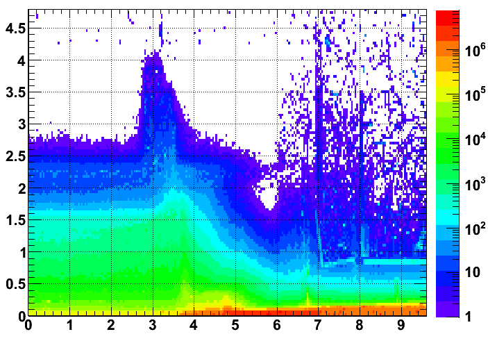
Figure: Simulated Total Annual Ionizing Dose, Gy/yr. Luminosity 1034 1/cm2s, energy 14 TeV, 107 s running per year, 2012 detector geometry.